Microport CRM-Sorin pacemakers in 20 points
Content
1) Case volume
Single chamber Kora 100 SR: 7.5 cm3
Double chamber Kora 100 DR: 8 cm3
2) Battery type
GB8711 Lithium Iodine (2.8 V, 0.81 Ah)
3) Wear and length criteria
Values expressed: frequency under magnet or pile impedance
Diagram (gauge, pile curve):
a. Stimulation frequency under magnet in min-1
b. Battery curve: Battery impedance (kOhms vs. time)
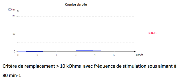
The Recommended Replacement Date (RRD), formerly known as the Elective Replacement Indicator (ERI), is defined by :
- a frequency under magnet ≤ 80 min-1
- battery impedance ≥ 10 kOhms
From ERI to end-of-life (complete exhaustion), the stimulator automatically sets itself to VVI mode, frequency at 70 min-1, stimulation and detection parameters programmed, servo and smoothing off.
Reprogramming is possible, but at the next daily battery impedance measurement, the stimulator reverts to the parameters described above.
4) Magnet Frequency
Start of life: 96 min-1
RRT (Recommended Replacement Time): 80 min-1
End of life: 73 min-1
Programming specifics magnet response:
Phase 1: magnet application (as long as magnet is applied)
- Frequency = Magnetic frequency
- Mode: DOO or VOO
- Stimulation parameters: 5 V / 0.5 ms / rest DAV
Phase 2 (Magnet removal): Capture test (6 cycles)
- Frequency = Magnetic frequency
- Mode: DOO or VOO
- Stimulation parameters: programmed amplitude and pulse duration / DAV = 95 ms
Phase 3 (Magnet removal continued): Frequency test (2 cycles)
- Frequency = programmed base frequency
- Mode: DOO or VOO
- Stimulation parameters: programmed amplitude and pulse duration / programmed AV delay
5) Traditional stimulation modes
All traditional modes are available.
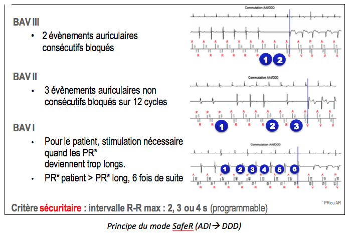
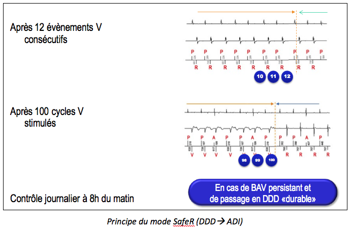
6) Special mode for spontaneous conduction: SafeR mode
ADI(R) è DDD(R) switching criteria: different criteria lead to switching to DDD mode: pause (programmable duration without VS), AVB III (2 consecutive atrial cycles without VS), AVB II (3 cycles out of 12 without VS), AVB I (patient PR > programmed long PR, 6 times in a row; can be programmed with effort or effort + rest);
DDD(R) and ADI(R) switching criteria: when the pacemaker is operating in DDD mode, it looks for the presence of an underlying proper rhythm. The stimulator switches back to ADI in 3 circumstances: after 12 consecutive ventricular events detected, systematically after 100 stimulated ventricular cycles, or after the sustained switching period that stops every morning at 8 a.m. The pacemaker switches permanently to DDD mode (until 8 a.m. the following day) in the event of persistent AVB: more than 45 AAI è DDD episodes per day, more than 15 AAI è DDD episodes per day for 3 consecutive days, more than 50% of the time spent in DDD in the last hour.
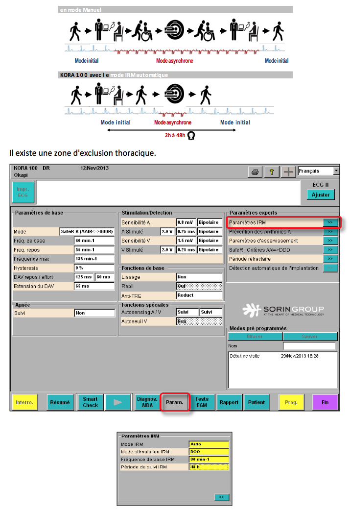
7) MRI mode
Principle
MRI mode is an asynchronous mode (DOO, VOO or OOO) which is triggered manually or when a strong magnetic field is automatically detected. The MRI mode operating period can range from 2 to 48 hours, depending on programming. If set to AUTO, the device recognizes the magnetic field as it passes through the MRI and automatically switches to MRI mode. Available MRI stimulation modes are : DOO, VOO, OOO.
8) Ventricular stimulation: autothreshold V
Autothreshold V on Auto: regular measurements of ventricular stimulation threshold + adaptation of programming; Autothreshold V on follow-up: regular measurements of ventricular stimulation threshold but without adaptation of programming.
Threshold systematically measured every 6 hours; capture control based on evoked response analysis; 4 threshold measurements per day with adaptation for the following 6 hours; automatic amplitude adaptation to twice the threshold value (100% safety margin) within a programmable minimum value (1.5, 2, 2.5, 3 or 3.5 V).
9) Atrial stimulation: no automatic measurement of atrial threshold
There is no Atrial autothreshold in the Reply, Reply 200 and Kora 100 generations, but this function should be available in the next version of Kora.
10) Sensitivity and detection
Atrial and ventricular detection can be set to fixed or autosensing.
Autosensing can be set to
- Tracking, which measures P-wave and R-wave amplitudes without adaptation of sensitivity settings, which remain fixed
- Auto, which measures P and R waves with automatic sensitivity adjustment: signal amplitude is averaged over 8 consecutive cycles and sensitivity is set to one-third of this average value.
11) Refractory periods
Following atrial stimulation, a 30 ms non-programmable refractory period is triggered at the ventricular stage. If ventricular detection occurs between the end of this refractory period and the end of the safety window (95 ms after the atrial stimulus), ventricular pacing is delivered at the end of the safety window.
Following atrial detection or stimulation, another non-programmable relative refractory period is triggered at the atrial stage. Its duration is dynamic and calculated as a function of the atrial rhythm. Its purpose is to detect acceleration of the atrial rhythm (hence its name: DARA window). There is no PVARP on Microport CRM-Sorin pacemakers. Following a ventricular detection considered as an PVC, a relative refractory period (the RetroPwatch) is triggered at the atrial stage. Its duration is 500 ms.
12) Diagnosis and interruption of pacemaker mediated tachycardias
The “Anti-PMT” algorithm is always active in atrial tracking mode (non-deprogrammable).
Initial detection phase over 8 cycles: the device measures retrograde conduction time (VP) and suspects an PMT if VP intervals are stable (to within 30 ms) and short (< 470 ms). Confirmation phase over 2 to 4 cycles: the device modulates the AV delay to verify VP interval stability.
Stop PMT by lengthening the relative atrial refractory period. If the anti-PMT option is set to “Reprog”, the resting and effort AV delays are automatically shortened.
13) Pacemaker dependency
Sorin pacemakers are equipped with 2 sensors that can work together or separately: an accelerometer and a minute ventilation sensor (transthoracic impedance measurement). When used simultaneously, the stimulation frequency is guided first by the accelerometer (better reactivity at the start of effort) and then by minute ventilation in the middle and end of effort.
14) Mode switch for atrial arrhythmias
The fallback function comprises three distinct phases: 1) a suspicion phase: as soon as a ventricular cycle with suspected atrial arrhythmia is detected, the fallback algorithm begins an analysis of 32 ventricular cycles. Atrial arrhythmia is confirmed if 28 or more ventricular cycles are suspected during the last 32 ventricular cycles (primary criterion) or if 18 or more ventricular cycles are suspected during the last two blocks of 32 ventricular cycles (secondary criterion); 2) a dissociation phase: once one of the fallback criteria has been reached, the pacing mode switches from synchronous to asynchronous (DDI); 3) reassociation phase: as soon as the atrial arrhythmia ceases and sinus rhythm resumes, the ventricular pacing frequency is gradually adapted to achieve sinus rhythm. A-V reassociation only occurs if atrial and ventricular rates are slower than 110 min-1.
15) Flutter management
No specific algorithm; when a 2/1 flutter occurs, it is necessary to shorten the duration of atrial blanking post ventricular pacing.
16) Atrial arrhythmia prevention
3 algorithms are available
Sinus rhythm overdrive: increase pacing frequency to overdrive spontaneous atrial activation.
ESA Pause Suppression and ESA Rate Acceleration: increase pacing rate following an PAC in order to avoid short-cycle, long-cycle succession.
17) Wireless communication
Technology not available on current platforms
18) Memory duration
Maximum EGM recording time: approx. 11 minutes with 512 Hz A and V sampling rate, 22 stored episodes, with annotated markers, synchronized to the endocavitary EGM.
19) Telemonitoring
No remote monitoring on current platforms; future project to remotely interrogate pacemakers using a telemetry device (to be placed opposite the pacemaker) linked to a transmitter connected to the Internet via the wired or GSM telephone network.
20) Other features
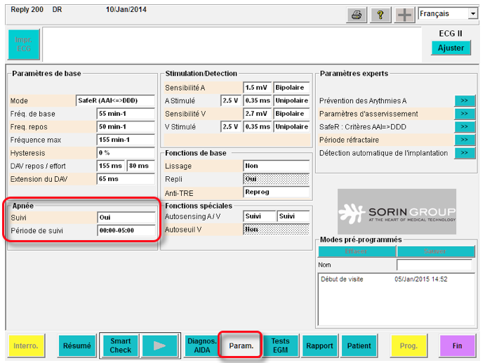
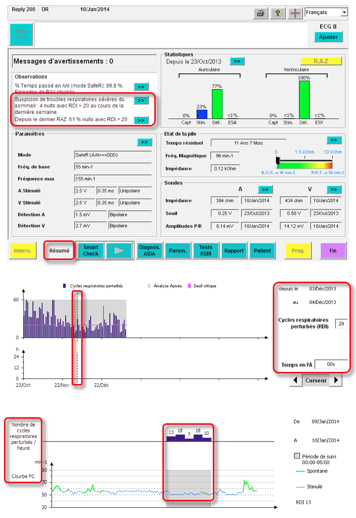
Sleep apnea monitoring: intrathoracic impedance data are measured using the MV sensor. Breathing cycle sequences are analyzed to identify, count and display disturbed breathing events during the night (programmable monitoring period). Two types of respiratory events are measured:
Breathing pauses: when the interval between two breathing cycles is greater than 10 seconds and less than 60 seconds.
Respiratory reductions: when Ventilation (VE, defined as the amplitude of a respiratory cycle divided by its period) is reduced by 50% or more compared with the mean VE for the previous 8 cycles, for more than 10 seconds and less than 60 seconds.
A respiratory disturbance index (RDI) is calculated by dividing the number of respiratory events by the number of hours of follow-up (5 hours). A critical threshold is used to indicate a suspicion of severe sleep-disordered breathing in the patient.
Sleep apnea monitoring is automatically activated the first time the stimulator is interrogated (after automatic implant detection).