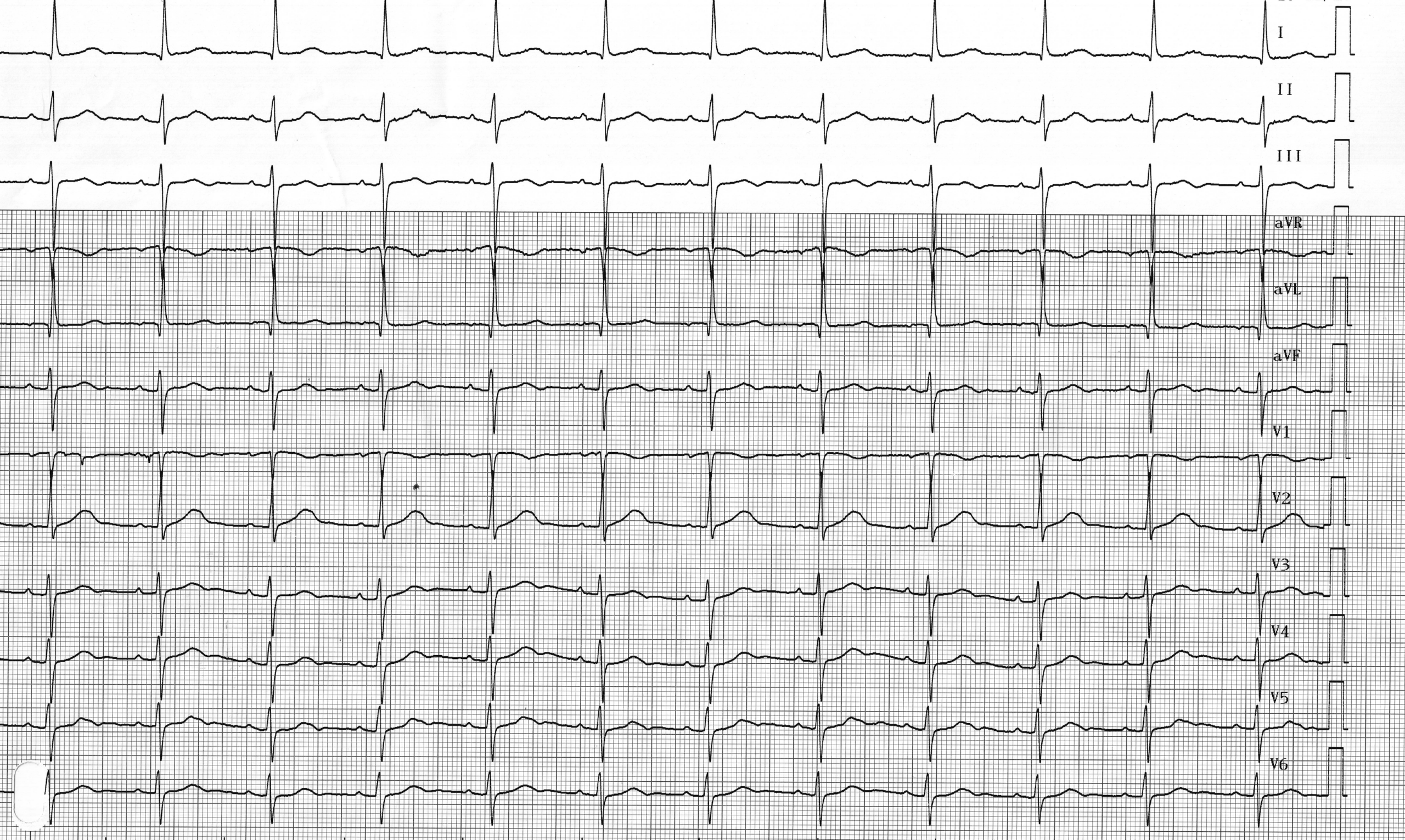
Un homme de 69 ans a reçu un stimulateur cardiaque double chambre Medtronic en raison de syncopes récurrentes dues à un dysfonctionnement du nœud sinusal ; les deux sondes sont bien positionnées, avec des impédances de stimulation normales, une détection correcte et des seuils de stimulation satisfaisants ; Trois jours après l’implantation, le stimulateur cardiaque a été contrôlé ; différents modes de stimulation ont été programmés et des tracés ont été enregistrés ; pour ce premier tracé, l’appareil a été programmé en mode 0D0
En ce qui concerne cet ECG, laquelle ou lesquelles des réponses suivantes sont correctes ?
Description de l'ECG
Contractions auriculaires spontanées et rythme sinusal (ondes P positives dans DI, DII, V5, V6 ; négatives dans aVR) ; intervalle PR normal et constant (< 200 ms) ; contractions ventriculaires spontanées avec signes d'hémibloc antérieur gauche (axe gauche, profil q1S3) ;
Explication
En fonction du nombre de sondes et du modèle du dispositif implanté, différents modes de stimulation peuvent être programmés. Le médecin traitant doit bien comprendre le fonctionnement, les avantages et les inconvénients propres à chaque mode de stimulation afin d’optimiser la programmation en fonction des caractéristiques individuelles de chaque patient implanté. Une collaboration entre la Société nord-américaine de stimulation cardiaque et d’électrophysiologie (NASPE) et le Groupe britannique de stimulation cardiaque et d’électrophysiologie (BPEG) a abouti à l’élaboration d’un code de classification international (NBG) pour les différents modes de stimulation. Les différents modes de stimulation sont identifiés par un code à quatre lettres qui décrit leur fonctionnement de base. La première lettre définit le ou les sites de stimulation : ventricule (V), oreillette (A), les deux (D), chambre unique (S) ou aucun (0). La deuxième lettre définit le ou les sites de détection : les mêmes lettres que ci-dessus. La troisième lettre indique le mode de fonctionnement : inhibé (I), déclenché (T), les deux (D) ou aucun des modes ci-dessus (0). La quatrième lettre indique la réponse à la fréquence (R) ou son absence (0).
Dans ce premier tracé, le stimulateur cardiaque a été programmé en mode 0D0. La particularité de ce mode de “ stimulation ” réside dans le fait que la détection est active dans les deux cavités, mais qu’aucune stimulation (auriculaire ou ventriculaire) n’est possible. Il ne doit donc évidemment pas être utilisé chez les patients dépendants. Ce mode de stimulation permet ainsi d’analyser le rythme spontané du patient avec visualisation simultanée de l’électrocardiogramme et des marqueurs d’événements. Il s’agit d’un mode de test de sensibilité. Le mode 0D0 peut être programmé temporairement chez les patients non dépendants équipés d’un stimulateur cardiaque compatible IRM et devant subir une IRM. Le mode 0D0 de ces stimulateurs cardiaques compatibles IRM empêche le passage potentiel d’un mode 0D0 traditionnel à un mode VVI. Il est bien sûr essentiel de vérifier et de reprogrammer le stimulateur cardiaque après l’examen (conformément aux instructions du fabricant).
Dans les formes d'onde suivantes, différents marqueurs sont utilisés :
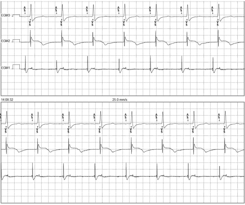
AS (détection auriculaire) : détection auriculaire ; VS (détection ventriculaire) : détection ventriculaire ; AP (stimulation auriculaire) : stimulation auriculaire ; VP (stimulation ventriculaire) : stimulation ventriculaire ;
Description du tracé
Il s'agit de l'enregistrement (simultanément à la trace précédente) d'électrogrammes intracavitaires à partir du programmateur ; l'EGM 3 correspond à une dérivation électrocardiographique, l'EGM 2 à l'EGM ventriculaire et l'EGM 1 à l'EGM auriculaire ; activité auriculaire et ventriculaire spontanée (AS-VS) ;
À retenir
Sur un stimulateur cardiaque bicaméral, différents modes peuvent être programmés, chacun présentant ses propres caractéristiques : mode D00 : pas de détection, stimulation asynchrone ; mode 0D0 : pas de stimulation ; mode DDT : mode déclenché, dans lequel une détection déclenche une impulsion de stimulation ; mode VDD : pas de stimulation auriculaire ; mode DDI : pas de stimulation ventriculaire après une détection auriculaire ; mode DDD : synchronisation ventriculaire avec détection auriculaire et stimulation ventriculaire ; modes spécifiques au fabricant visant à éviter toute stimulation ventriculaire inutile ;