Testing an implanted lead comprises analysis of the impedance, threshold and sensing capabilities, comparing it with previously recorded values. This is no different for the LV lead lead in exception for sensing, as the LV lead is not used for sensing in MicroPort devices (only in Biotronik and Boston Scientific CRT devices).
LV threshold test
The test is very similar to the RV lead threshold test, it is launched in DOO mode with a starting output (3.5V in the example) which decreases in steps of 0.25V untill the last value of 0.25 V. Similar to RV threshold testing, the testing rate is 90 bpm at the programmed polarity (LV-tip to RV-coil in this case) and pulse width (0.35 ms by default). Once the test is performed, the tracing is frozen and it is possible to reanalyze the EGM. The selected threshold values are the last amplitude values (Volt) which captured the LV. Click on the corresponding pacing output, or select it with the right or left arrow keys on the keyboard (blue bar in the figure below). It is necessary to save the test results after each test, these being reported in the test assistant table and in the « Leads » table of the « Summary » screen. See live examples of LV threshold testing in our interrogation videos. After the LV threshold test, the phrenic nerve stimulation threshold can be stored (when present) together with the left pacing threshold. When multipoint pacing is enabled, the pacing test is divided into LV MP1 and LV MP2 as programmed. However, multipoint pacing (pacing the LV at multiple sites) is currently not recommended as it uses more energy and it’s benefits remain to be shown.
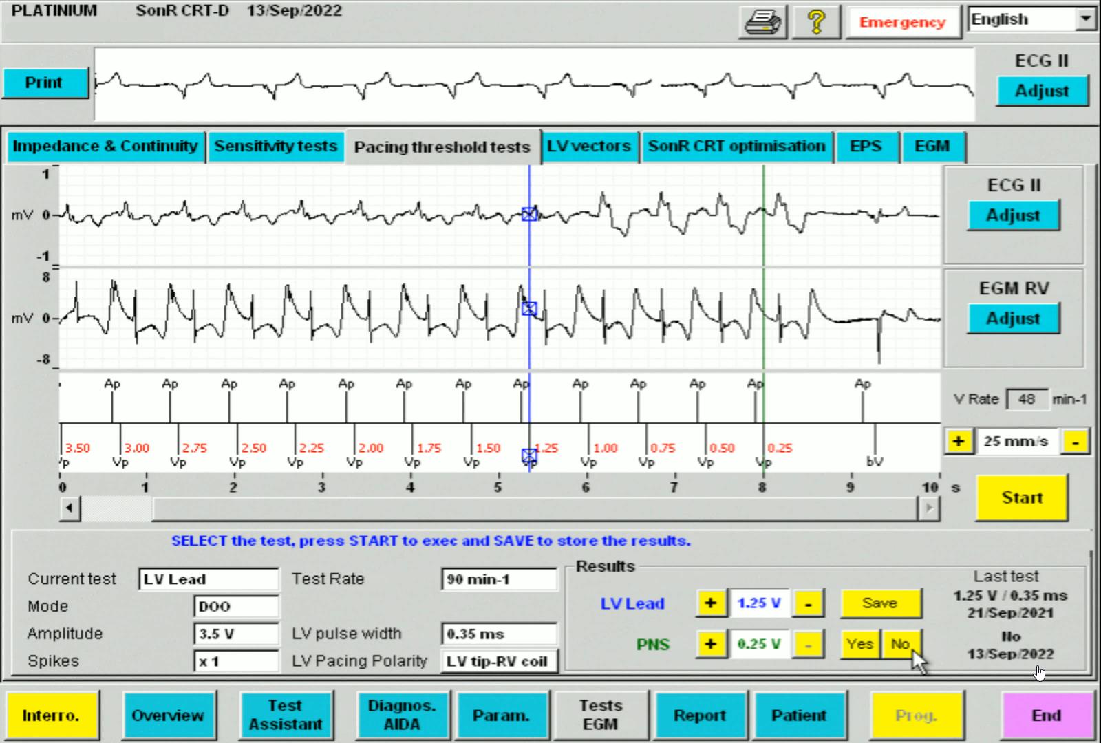
In this example the LV-tip to RV-coil pacing threshold is 1.25V. There was no phrenic nerve stimulation (PNS), PNS “No” was selected but this is not mandatory, it will show up empty in the list when nothing is saved. However it is important to save the value at which PNS occurs, as this makes selecing the best vector easier.
LV pacing vectors
The next tab in the tests screen is « LV Vectors ». The assistant displays the following: in the table on the left of the screen, are shown the last impedance measurements for each vector, the LV pacing threshold, and the phrenic nerve stimulation (PNS) threshold, and on the right of the screen, the LV vector(s) and LV pacing parameters that are currently programmed. Simply check the vectors in the table on the left that you wish to test, choose the test rate, then click on « LV test: Start » to begin. The threshold test screen opens and click start to run the test. The pacing and possibly the phrenic nerve thresholds are recorded, then click on the « NEXT » button to test the following vector and so on. At the end of the tests, the LV Vectors screen displays the results. You can then select the vector(s) you wish to program, then click on « Apply » and display the Brady parameters screen. The selected values appear in yellow. Click on the « Prog » button to program the selection.
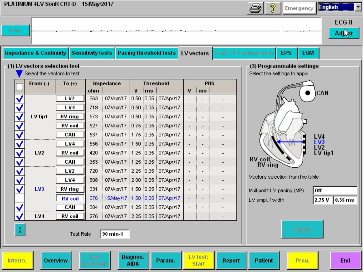
The LV vectors screen enables a quick overview of impedances, LV pacing thresholds and phrenic nerve stimulation (PNS) thresholds. Multiple vectors may be selected and tested semi-automatically one-by-one.
EGM Tab
The last tab, « LV Vectors » allows you to view the atrial and RV EGMs, markers and ECG at the same time. This may be used as a final check that every is working properly, excluding intermittent RV/LV capture problems and evaluating the presence of extrasystoles which may decrease %CRT.
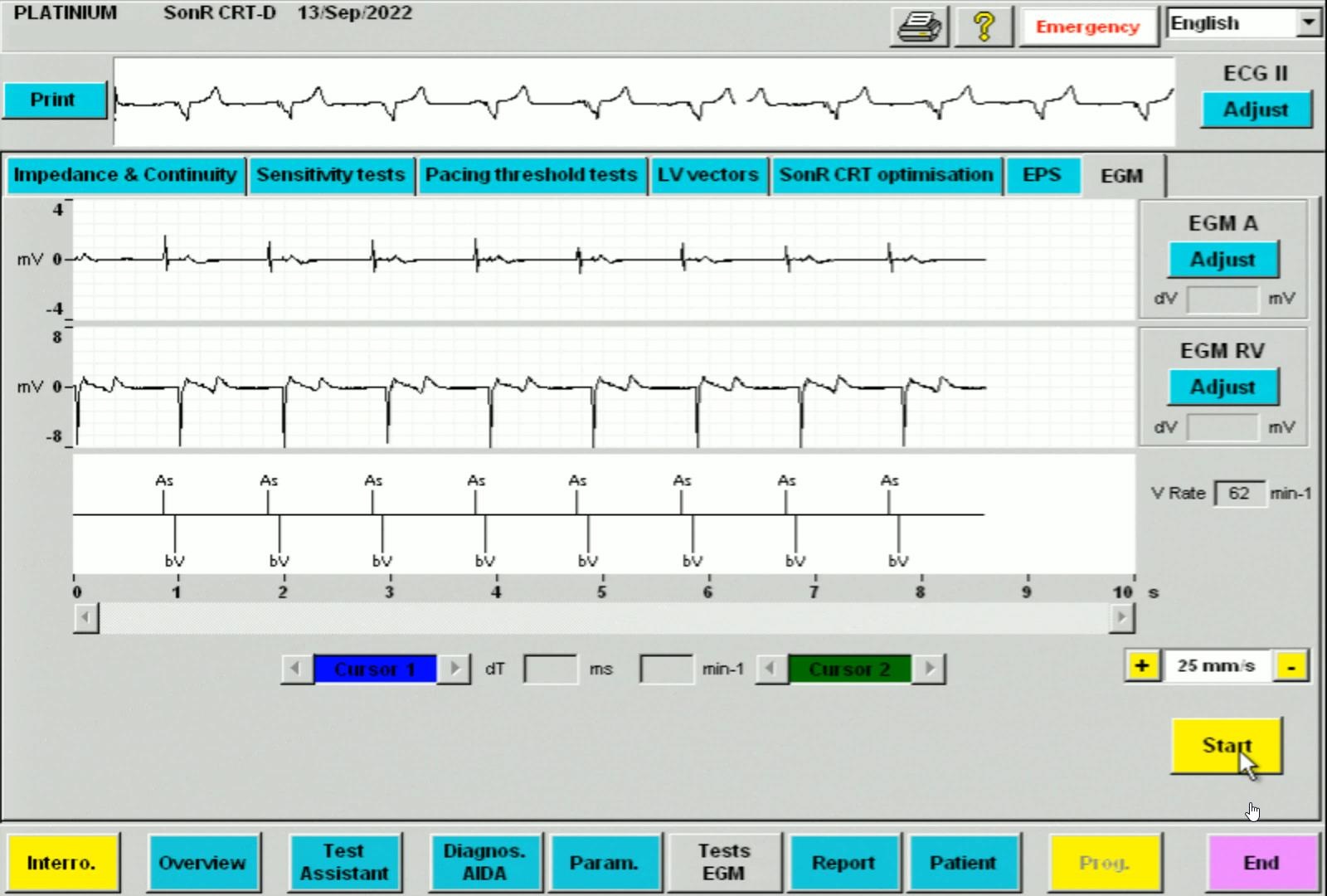
The EGM screen shows exclusively As-Bv markers, the ECG is also stable.
The function of the automated LV threshold is often very close to that described for the RV lead. The threshold measurement is based on the analysis of the evoked response, or by observing the synchronization of the RV events sensed after a stimulated LV event. The threshold is measured at regular intervals, depending on the manufacturer, after which a safety margin is programmed, without further cycle-by-cycle verification of capture. It is noteworthy that Microport dual and triple chamber devices do not verify the cycle-by-cycle LV or RV lead capture.
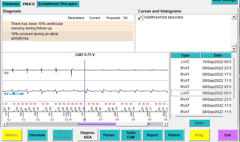
Example of automatic LV pacing test. LV pacing is performed with decreasing pacing output until there is a clear change in the QRS complex on the far field channel. The device recognizes a loss of capture and saves the preceding pacing output (0.75V in this case) as the LV pacing threshold.
The « Param. » button in the function bar at the bottom of the programmer screen allows access to the programming parameters for bradycardia, tachycardia and remote monitoring. The first screen to appear is the antibradycardia pacing parameters, most of which are described in the corresponding pacemaker courses. We will discuss the pacing parameters specific to CRT.
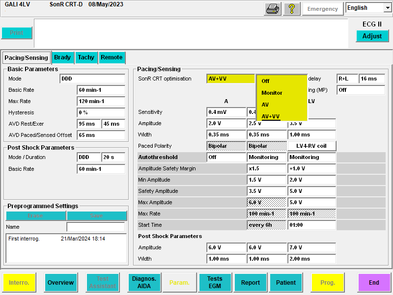
« SonR CRT Optimisation » tab
Under the « SonR » section, we find the « SonR CRT optimisation » parameter with 4 possible options: « Off », « Monitor » for which the algorithm processes the data and proposes optimal values, « AV » which automatically reprograms the AV delays, and « AV + VV » which automatically reprograms the AV delays and VV intervals. Find more about SonR in the AV/VV optimization course.
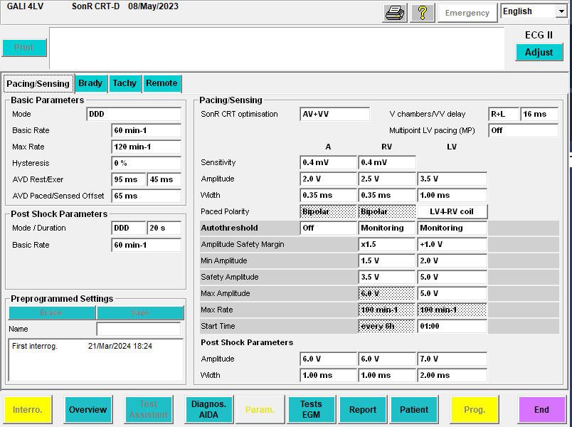
« V Chambers/VV delay » tab
Under the « Pacing/Sensing » section, we find the « V Chambers/VV Delay » parameter. It allows choosing monoRV (« R »), monoLV (« L »), biV ( «R + L » or « L + R » pacing, defining the order of occurrence of ventricular pacing spikes if a VV interval differing from 0 is applied). The VV delay is chosen between 0 and 64 ms in incremental steps of 8 ms.
« Multipoint LV pacing (MP) » Tab
The « Multipoint LV pacing (MP) » parameter can be used if a quadripolar left ventricular lead is implanted. « Off » means that only one electrode is used as a cathode on the LV lead, i.e. the left ventricle is paced only at one site. « On » means that two LV electrodes are used as cathodes on the LV lead, enabling the left ventricule to be paced at 2 separate sites. When a quadripolar lead is implanted, 14 pacing vectors are available for the pacing polarity.
Between 2010 – 2020 there were many studies investigating the potential beneficial effects of MP pacing but results were controversial. The idea is that adding a second area of LV capture, the LV is activated faster, optimizing CRT. While technically true, the beneficial effects on LV pump function are highly controversial. In addition, multipoint pacing more than doubles LV pacing output, draining the battery faster. Current ESC guidelines on pacing and CRT do not recommend MP pacing.
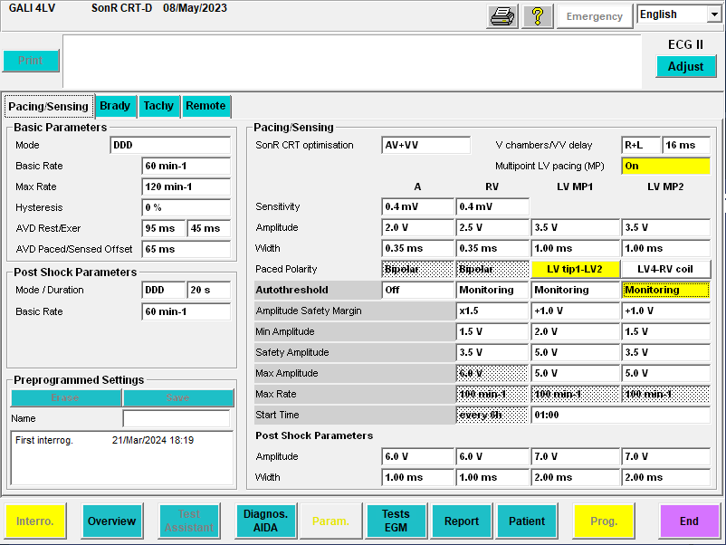
When clicking « On » in the « Multipoint LV pacing (MP) » tab, two LV lead electrodes are hence used as cathodes on the LV lead, with the respective LV pacing polarities, amplitude and pacing width for each of the LV pacing dipoles « MP1 » and « MP2 » appearing on the screen.
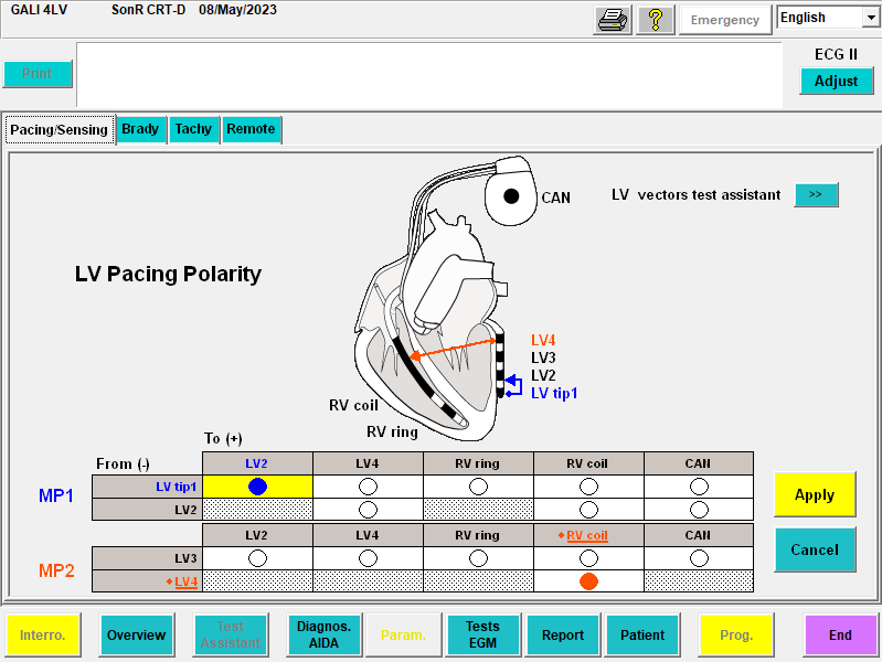
Clicking on any of the « LV pacing polarity » tabs opens a new screen allowing the selection of the LV pacing electrodes, aided by a diagram. If you wish to program, clicking on « Apply » returns to the pacing parameters screen allowing the programming of the selection made.
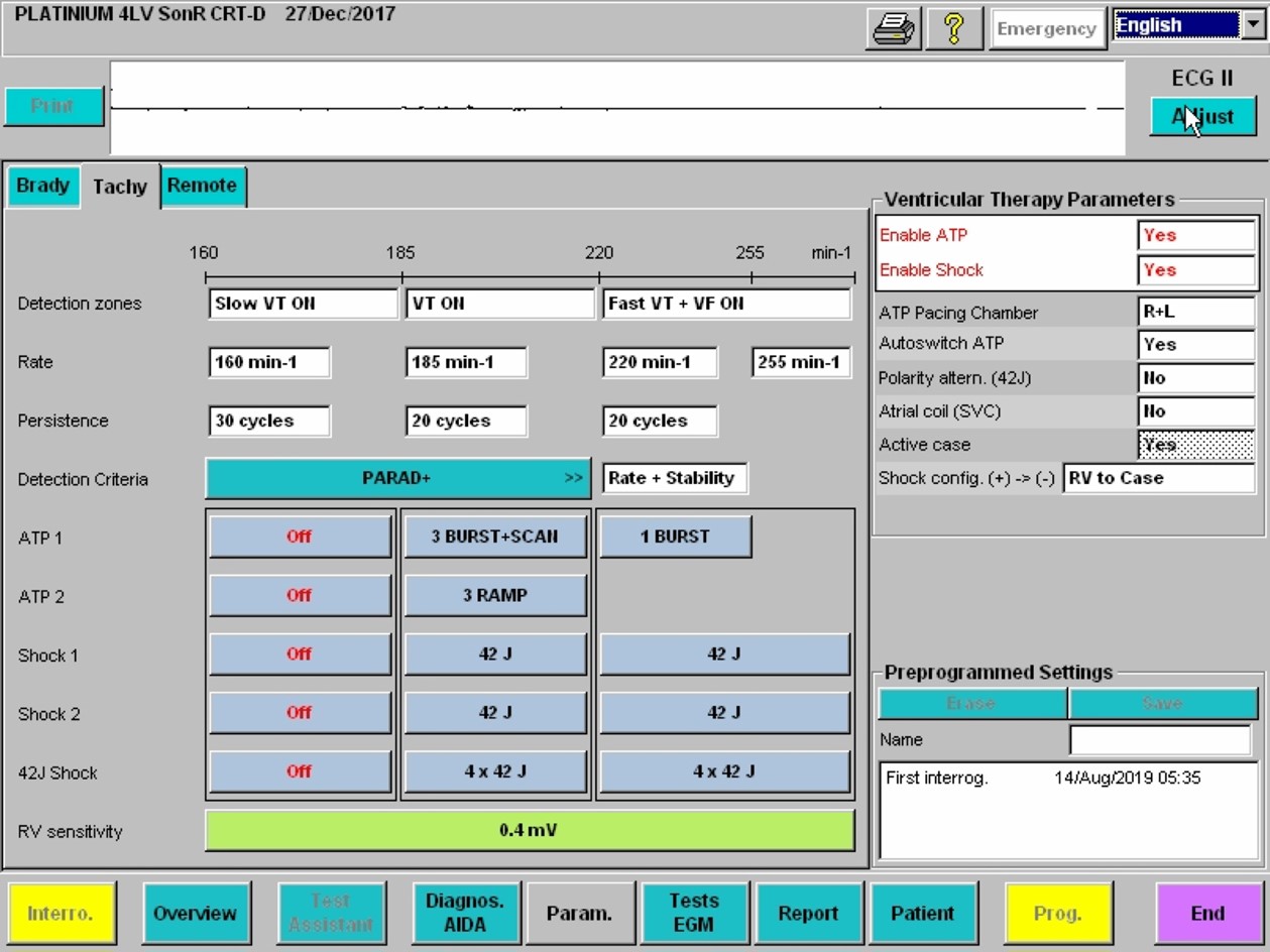
Tachy tab
Under the tachy tab, the ICD parameters may be programmed, these are discussed in the ICD courses. In CRT devices, it is possible to choose the ventricular pacing configuration for ATPs, which is independent of pacing: « R » for RV, « L » for LV, « R+L » for biV. The VV delay is forced to 0 ms during a biV ATP. It is recommended to keep this setting on “R+L” as literature indicates it is more effective. If you wish to know more about ATP, we highly recommend this video by Dr Josh Cooper.