

Boston Scientific subcutaneous ICD - Preimplantation screening
Content
The subcutaneous ICD needs a manual screening procedure to determine a patient’s eligibility for subcutaneous defibrillator implantation. Inappropriate shocks, mainly due to T wave oversensing, were relatively common in early versions of subcutaneous defibrillators. Similarly, a small number of the very first procedures ended in failure due to the inability to obtain an R wave amplitude compatible with satisfactory detection. A few small studies have identified certain characteristics that contribute to poor subcutaneous recording quality (hypertrophic cardiomyopathy, electrolyte disturbances, obese patients, etc.), but with a fairly low predictive value, suggesting the need for individualized screening to identify unsuitable candidates for this type of device prior to implantation. There is a close correlation between skin electrograms and subcutaneous electrograms in terms of R-wave and T-wave amplitude, suggesting the possibility of predicting the quality of subcutaneous recordings from surface electrocardiographic recordings.
A screening test is now routinely performed on all candidates who may benefit from the implantation of a subcutaneous defibrillator in order to optimize sensitivity and specificity and exclude patients who do not have the electrocardiographic characteristics required for the device to function properly.
ECG ruler screening
Preimplantation screening can be performed manually using a ruler supplied by Boston Scientific, which is very similar in format to a standard ECG ruler. This ruler (model 4744) includes markings for measuring heart rate (standard ECG ruler), a guide indicating the 14 cm measurement to be used for positioning surface electrodes during the screening test, and six colored profiles of different morphologies. Each color profile has an identical window above and below the baseline for analyzing positive deflections (R waves, P waves, T waves) and negative deflections (S waves, inverted T waves).
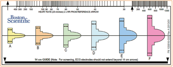
The ruler is positioned on the analyzed recording, initially searching for the color profile that best matches the amplitude of the QRS complex. The horizontal line is aligned with the isoelectric baseline and the left edge of the profile is aligned with the start of the QRS.
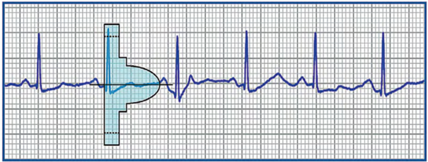
For the vector to be validated, the maximum amplitude of the QRS complex must fall within the window delimited by the dotted line and the peak of the colored profile, and the entire QRS complex and T wave must be contained within the colored profile. For biphasic (RS) signals, the largest peak must be used. These colored profiles correspond to the sensitivity modification profile subsequently used by the device for the shock zone. This is therefore the most sensitive profile, as the objective of screening is to place oneself in the “worst conditions” that maximize the risk of oversensing.
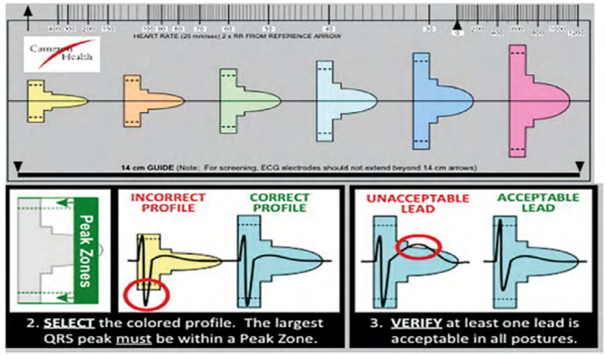
Various electrocardiographic profiles are associated with vector invalidation: R wave amplitude too low or too high, T wave or P wave too wide. A vector is invalid if: 1) with a maximum amplification of 20 mm/mV, the maximum amplitude of the QRS complex is too low to fit within the window delimited by the dotted line and the peak of the smallest colored profile (yellow); the minimum voltage required for QRS complexes is 0.25 mV; 2) with a minimum amplification of 5 mm/mV, the maximum amplitude of the QRS complex is too high to fit within the window delimited by the dotted line and the peak of the largest colored profile (pink); a maximum voltage of 3.6 mV for QRS complexes is accepted; 3) when the maximum amplitude of the QRS complex fits within the window delimited by the dotted line and the peak of the adapted colored profile, part of the QRS complex, P wave, or T wave is outside the colored profile.

Emblem S-ICD automatic screening tool
The Emblem S-ICD automatic screening tool (model 2889), which is software used on Zoom Latitude programmers (model 3120), presents an alternative to manual screening performed with a ruler. Performing automatic screening using the Boston Scientific™ programmer eliminates the “human” subjectivity of the ruler test and standardizes the filters used (for the manual test, different filters are used depending on the ECG device). In addition, vector validation is performed using the same digital filters, the same gains, and the same detection algorithm (Vector Select) that will then be used by the implanted device, which theoretically optimizes the efficiency of the procedure.
Automatic screening takes place in several stages:
- Careful preparation of the skin before placing the surface electrodes;
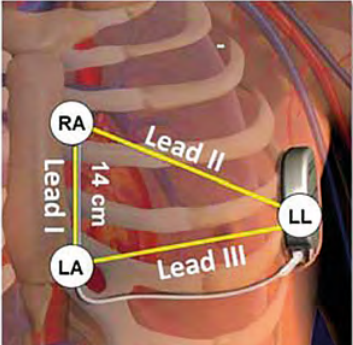
- Positioning of the three skin electrodes at the detection poles so as to mimic the three future vectors available once the device is implanted; the LL (Left Leg) electrode corresponding to the box must be positioned laterally at the fifth intercostal space (between the fifth and sixth ribs) on the left mid-axillary line; The LA (Left Arm) electrode corresponding to the proximal electrode must be positioned approximately 1 cm to the left of the xiphoid process of the sternum. The RA (Right Arm) electrode corresponding to the distal electrode must be placed 14 cm higher than the previous electrode on the left parasternal line (a guide indicating 14 cm is shown on the ruler provided by the manufacturer). A fourth electrode (ground) can be positioned away from these three electrodes (at the level of the right clavicle, for example).
- Select the position of the sternal probe that corresponds to the vertical part of the implanted electrode (left, right, or middle sternal margin).
- The supine position (torso in a horizontal position) must be used.
- The sitting or standing position (torso in a vertical position) must be used.
- If necessary, perform a test in another position or context (e.g., during exercise).
- Record DI, DII, and DIII leads for 10 to 20 seconds at a scroll speed of 25 mm/s using the programmer.
The automatic screening report includes:
- a summary with the results for the validation of 3 vectors in the different positions;
- 15 seconds of tracings for the 3 vectors and for the different positions tested.
The automatic screening procedure is simple to perform, requires no particular learning curve, and offers high inter-observer reproducibility. The electrode placement site must be carefully prepared, hair removed, and the skin cleaned using an alcohol-free wipe or skin preparation gel. It is essential to obtain a trace with a stable baseline, free of noise or motion artifacts. It is preferable to use electrodes whose packaging has not been opened beforehand, as the electrodes may have dried out. If the baseline fluctuates or the trace is noisy, it may be helpful to re-abrade the skin at the electrode sites and ask the patient to inhale and then hold their breath temporarily to eliminate the respiratory artifact.
When the three electrodes are connected for the screening procedure, the programmer calculates the heart rate from the secondary vector. If there is interference on this lead and the heart rate is falsely measured at over 240 bpm, the screening procedure cannot be performed. A vector is validated during the screening procedure if:
- the morphology of the QRS-T complex is validated in all positions tested (at least in the supine position and in the sitting or standing position; 90° difference in torso position);
- the morphologies of the different QRS complexes that can be observed in the same patient (spontaneous QRS and stimulated QRS in a patient with a pacemaker) are all validated in the different positions;
- there is no significant variation in the morphology of the QRS complex or T wave between the supine and standing positions (stable morphology without postural variations);
The morphology of the QRS complex is not only used to distinguish the origin of arrhythmias in the conditional zone (VT versus SVT), but also during the certification phase to classify the detected complexes as certified (included in the heart rate calculation) or suspicious (excluded from the heart rate calculation) and to avoid overdetection of the T wave or double counting of the R wave; morphology analysis is therefore central to the functioning of the device (much more so than for an endocavitary defibrillator) since it is integrated into the classification of cycles; a postural variation in the appearance of the QRS complex is therefore incompatible with correct functioning; a positional change in the amplitude of the QRS complexes probably does not justify the vector being considered invalid; on the other hand, a change in axis (QRS complex positive in one position and negative in the second, or vice versa) justifies the vector being considered invalid.
Screening for right sternal implantation
In some patients who are not eligible for traditional electrode placement (left of the xiphoid process for the proximal electrode and on the left parasternal line for the distal electrode), it may be proposed to move the defibrillation probe to the right side of the sternum, which modifies the detection vector by increasing the spacing between the probe electrodes and the device.
However, when deciding to change the location of the electrodes, it must be taken into account that changing the position of the paddle also changes the defibrillation vector, which can directly affect its effectiveness. The effectiveness of defibrillation has been validated in many patients with a left parasternal paddle, but its effectiveness with a paddle positioned on the right has only been validated in a few isolated cases. The effectiveness of defibrillation must therefore be verified during a VF induction procedure.
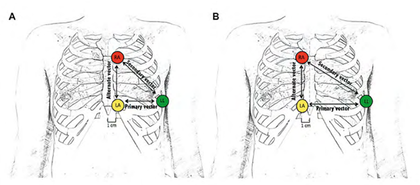
Position A corresponds to the classic position, and position B is an alternative right lateral sternal position proposed when no vector is validated in position A.
In some centers, the screening procedure is systematically performed in both the left and right positions. In fact, in some tall patients with a downwardly deviated apex, a conventional probe position to the left of the sternum may not be optimal during implantation, as a position to the right of the probe allows a wider myocardial area to be covered. It is therefore useful to know that at least one vector is validated with this alternative probe position. It is possible to test other probe positions if the previous two do not yield at least one valid vector, but there are a number of limitations:
- lower probe: increased risk of oversensing of myopotentials from the rectus abdominis muscle;
- higher probe: increased risk of externalization;
- more lateral probe on the right or left: increased risk of oversensing of myopotentials originating from the pectoral muscle.