Stimulation ventriculaire
Généralités
Informations générales
Définition du seuil de stimulation
Le seuil de stimulation correspond à la plus petite impulsion électrique, délivrée en dehors de toute période réfractaire naturelle, capable de générer la propagation d'une dépolarisation. Il peut être mesuré en tension (volts) ou en largeur d'impulsion (millisecondes).
Chronaxie et rhéobase
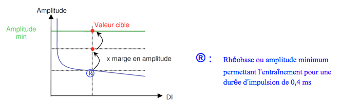
La relation tension-durée de Lapicque, ou chronaxie-rhéobase, décrit la relation non linéaire entre la tension de seuil et la durée de l'impulsion. L'amplitude au seuil de stimulation augmente de manière significative avec la diminution de la durée de l'impulsion (en pratique en dessous de 0,2 ms). Tous les points définis par la tension et la durée d'impulsion au-dessus de la courbe sont associés à une stimulation efficace, tandis que ceux situés en dessous ne le sont pas.
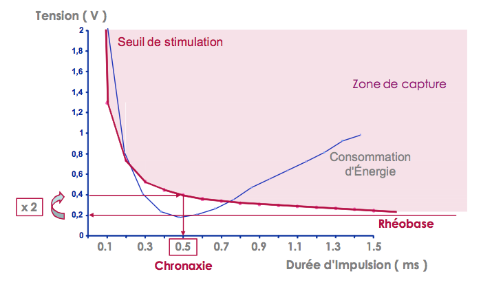
La rhéobase est la plus petite tension efficace pour une durée d'impulsion infinie (en pratique, supérieure à 2 ms).
La chronaxie est la plus petite durée d'impulsion effective pour une tension deux fois supérieure à la rhéobase. La consommation d'énergie est minimale pour une durée d'impulsion correspondant à la chronaxie.
La chronaxie et la rhéobase qualifient électriquement une électrode de stimulation. Aujourd'hui, les valeurs de chronaxie sont comprises entre 0,3 et 0,4 ms, quelle que soit la sonde utilisée ; cette valeur correspond à la largeur d'impulsion nominale habituelle des stimulateurs. La chronaxie est souvent plus longue sur les électrodes de stimulation ventriculaire gauche.
Le seuil de stimulation est généralement plus bas lorsque la tension est progressivement diminuée que lorsqu'elle est progressivement augmentée : c'est l'effet Wedensky.
Paramètres influençant le seuil de stimulation
Activité
L'accélération de la fréquence cardiaque peut abaisser le seuil. Pendant l'exercice, le seuil peut être légèrement abaissé par les catécholamines. Le sommeil et les phases postprandiales l'augmentent.
Médicaments et troubles métaboliques
Les glucocorticoïdes, l'épinéphrine, l'éphédrine et l'isoprotérénol abaissent le seuil, tandis que le propranolol, le vérapamil, la spirinolactone, la quinidine et l'amiodarone ne le font pas. Les antiarythmiques de classe IC (flécaïnide et propafénone) peuvent augmenter considérablement le seuil. Toute modification du traitement médical devrait, en théorie, conduire à une vérification du seuil de stimulation.
L'hyperkaliémie, l'hypoxie, l'hypercapnie, l'hyperglycémie, l'acidose ou l'alcalose métabolique augmentent le seuil de stimulation.
Degré de fibrose
Lors de l'implantation, le traumatisme direct de l'électrode sur l'endocarde crée un courant de lésion et une élévation du seuil qui ne dure que quelques minutes. Avant l'utilisation des sondes à élution stéroïdienne, une élévation des seuils de stimulation dans les 6 premières semaines après l'implantation était fréquemment observée, en raison du phénomène inflammatoire induit par le traumatisme de l'électrode. Pendant cette période, des valeurs élevées d'amplitude de stimulation étaient programmées pour garantir une marge de sécurité adéquate. Depuis l'avènement des sondes à élution stéroïdienne, les seuils de stimulation sont restés stables dès la phase post-implantation, permettant de programmer une tension de stimulation nominale de 2,5 Volts.
À plus long terme, et en raison d'une réaction inflammatoire chronique aux corps étrangers, un tissu de fibrose se développe à proximité de l'électrode en contact avec l'endocarde, éloignant l'électrode des cellules myocardiques excitables. Le seuil de stimulation a donc tendance à augmenter avec le temps, même si les sondes modernes offrent des seuils beaucoup plus stables que par le passé. Cette possible augmentation des seuils conduit alors à la programmation d'énergies de stimulation plus élevées, et donc à une réduction de la durée de vie de la batterie. Dans ce contexte, il est possible d'utiliser un algorithme d'adaptation automatique de l'énergie délivrée, permettant une stimulation myocardique juste au-dessus du seuil de stimulation, avec un contrôle continu cycle par cycle ou quotidien de l'efficacité.
Influence de la configuration des électrodes sur le seuil et l'impédance
La taille, la forme et le matériau des électrodes influencent le seuil de stimulation. La densité de courant appliquée à l'électrode distale doit être aussi élevée que possible pour réduire le seuil. Cette densité de courant est la plus élevée sur les bords de l'électrode. Ainsi, une électrode sphérique est associée à un seuil plus élevé qu'une électrode annulaire.
Selon la formule E = U2 x t /Z, plus l'impédance de stimulation est élevée, plus la consommation de courant est faible. L'impédance de stimulation représente la somme des forces qui s'opposent à la circulation du courant dans un circuit électrique.
Il est composé de 3 résistances ohmiques :
- la résistance du conducteur (qui doit être aussi faible que possible, car le courant dépensé pour surmonter cette résistance est perdu en pure perte et en chaleur) ;
- la résistance de l'électrode (qui doit être la plus élevée possible pour réduire la consommation de courant et prolonger la durée de vie de la batterie). Plus le rayon de l'électrode est petit, plus la résistance de l'électrode est élevée, ce qui augmente la densité du courant et réduit le seuil de stimulation ;
- l'impédance de polarisation, qui doit être la plus faible possible.
Une surface poreuse avec une grande surface microscopique recouvre l'électrode pour 1) maintenir un petit rayon de courbure et donc augmenter sa résistance 2) réduire l'impédance de polarisation.
Influence de la polarité
La stimulation cathodique génère un seuil plus bas que la stimulation anodique.
En effet, la stimulation cathodique crée une diminution de la différence de potentiel transmembranaire des cardiomyocytes, alors que la stimulation anodique crée une hyperpolarisation, suivie d'une dépolarisation, avec une augmentation de la quantité d'énergie nécessaire.
En outre, les périodes réfractaires naturelles sont plus courtes avec la stimulation anodique, ce qui est associé à un risque arythmogène théorique plus élevé, en particulier dans les situations à haut risque telles que l'ischémie ou l'hypoxie.
L'anode d'une sonde de stimulation est théoriquement flottante ; le risque de stimulation anodique est donc très faible, mais il est observé lorsque l'anode est en contact avec la paroi et que l'amplitude de la stimulation est élevée. .
The threshold for unipolar stimulation is generally lower than for bipolar stimulation.
Influence de la forme d'onde de stimulation
La stimulation antibradycardique est réalisée à l'aide de stimuli monophasiques. Le seuil de stimulation monophasique est plus bas que le seuil de stimulation biphasique.
Le concept de seuil automatique et de capture automatique
La détermination du seuil de stimulation est d'une grande importance, car la programmation de la tension et de la durée des impulsions affecte la marge de sécurité et détermine la consommation d'énergie de la prothèse et donc le taux d'usure de la batterie. Il est généralement recommandé de programmer une marge de sécurité de 100%, ce qui correspond à deux fois la tension de seuil. Cette marge de sécurité est destinée à prendre en compte les variations circadiennes du seuil de stimulation, qui varie d'un sujet à l'autre en fonction du sommeil, des repas, de l'activité physique, de la fièvre, etc.
Tous les stimulateurs modernes peuvent maintenant être programmés avec une fonction de mesure automatique du seuil ventriculaire, qui peut être combinée ou non avec un ajustement automatique de l'amplitude de stimulation avec vérification cycle par cycle de l'efficacité de la capture (modèle Autocapture permettant de délivrer des amplitudes très proches du seuil avec une stimulation de sécurité de forte amplitude en cas de perte de capture) ou une adaptation pour des périodes prolongées après des vérifications planifiées du seuil mais sans vérification cycle par cycle (modèle Autothreshold exigeant des marges plus importantes).
Informations spécifiques à la marque
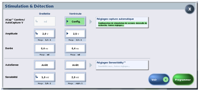
- Tous les stimulateurs cardiaques modernes permettent une mesure automatique du seuil de stimulation, avec une adaptation automatique de l'amplitude délivrée.
- Pour les 5 principales sociétés, l'évaluation de la capture ventriculaire est basée sur l'analyse de la réponse évoquée (différenciation entre la polarisation et la réponse évoquée).
- Les stimulateurs cardiaques Biotronik, Boston Scientific et Abbott disposent d'un contrôle cycle par cycle de l'efficacité de la capture, ce qui leur permet de délivrer des amplitudes très proches du seuil mesuré.
- Pour les stimulateurs Medtronic et Microport CRM-Sorin, le seuil est mesuré périodiquement et l'amplitude est adaptée en conséquence, sans vérification cycle par cycle de la capture, ce qui nécessite des marges de sécurité plus importantes.
Abbott
Principes de fonctionnement
- AutoCapture ventriculaire en marche : mesure du seuil de stimulation ventriculaire + adaptation de la programmation avec contrôle cycle par cycle ;
- seuil mesuré systématiquement au moins toutes les huit heures (autre programmation possible : mesure toutes les 24 heures)
- contrôle cycle par cycle de la capture basé sur l'analyse de la réponse évoquée
- marge de sécurité de 0,25 V
- amplitude maximale pouvant être délivrée : 4,5 V pour une durée d'impulsion programmée
L'auto-capture ventriculaire en pratique
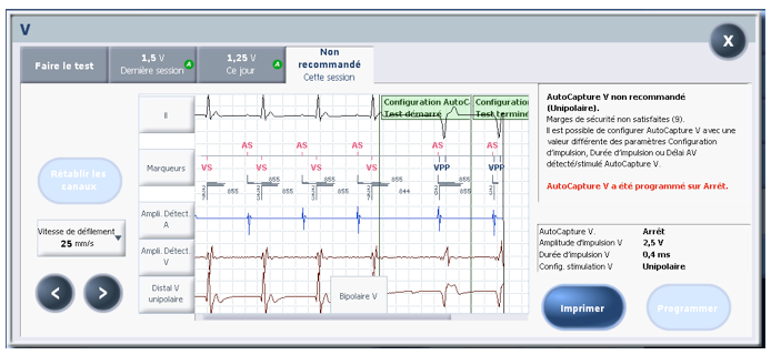
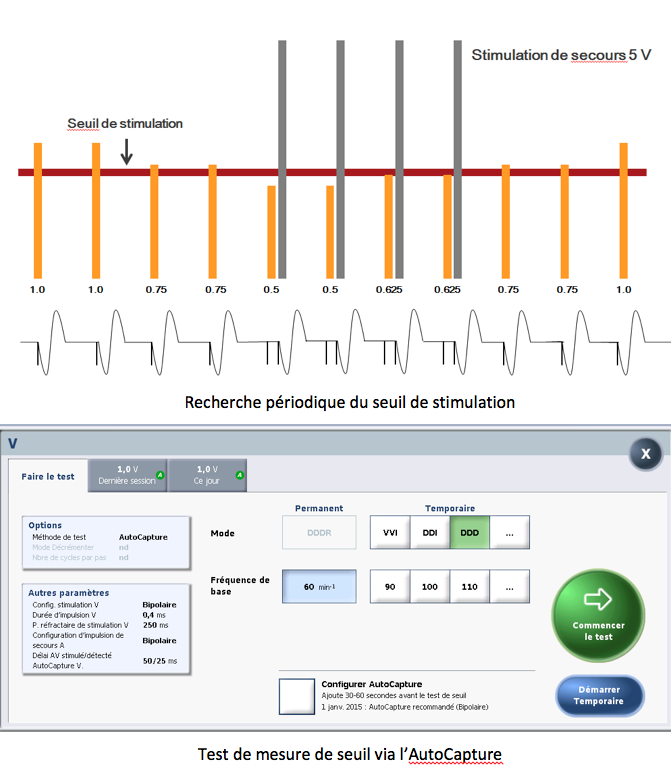
Le système de stimulation ventriculaire AutoCapture règle automatiquement l'amplitude de l'impulsion ventriculaire du stimulateur au-dessus du seuil régulièrement mesuré par le patient (au moins toutes les huit heures) et permet de vérifier la capture cycle par cycle. .
Depuis la plateforme de stimulateurs cardiaques Zephyr (et les gammes suivantes : Accent, Endurity, Assurity), AutoCapture peut être activé quelles que soient les configurations de détection et de stimulation programmées : Uni pacing/détection Uni ; Bi pacing/détection Bi ; Bi pacing/détection Uni ; Uni pacing/détection Bi.
Avant la première demande d'activation, un test de configuration automatique est effectué pour vérifier la compatibilité de la sonde en fonction de la polarisation et pour différencier la capture de l'échec de la capture. Ce test est facultatif (mais recommandé) avant chaque mesure de seuil.
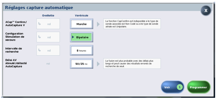
Trois réglages AutoCapture V sont disponibles :
- Configuration : ce paramètre est disponible lors de la première activation. Le programmateur propose alors de lancer le test de configuration, puis le test de stimulation si la capture automatique est recommandée ;
- On : l'appareil mesure le seuil, ajuste automatiquement l'amplitude de l'impulsion et enregistre la mesure du seuil dans la courbe du seuil, et mémorise l'EGM correspondant au dernier seuil ;
- Off : l'appareil ne mesure pas le seuil de stimulation et n'ajuste pas automatiquement l'amplitude de l'impulsion.
Les paramètres suivants peuvent être définis dans la fenêtre Paramètres de capture automatique :
- backup pacing configuration which programs the polarity configuration of backup pacing to bipolar or unipolar (nominal value);
- intervalle de recherche qui programme la périodicité de la mesure du seuil à 8 heures (valeur nominale) ou 24 heures ;
les délais AV stimulés/détectés pour AutoCapture™ V qui programment le délai AV stimulé et le délai AV détecté. - Paramètres de retard utilisés lors d'une recherche de seuil à 50/25 ms (valeur nominale) ou 100/70 ms ou 120/100 ms. Il est recommandé de régler ce paramètre sur 50/25 pour éviter les fusions. La fusion est plus probable avec des délais plus longs et peut conduire à des résultats de recherche de seuil incorrects.
Le système AutoCaptureTM utilise 4 algorithmes pour contrôler la capture cycle par cycle :
- Vérification de la capture
- Récupération des pertes de capture
- Éviter la fusion
- Mesure périodique du seuil de stimulation
1. Vérification de la capture
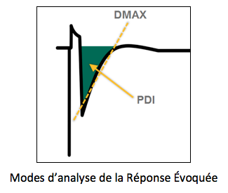
La vérification de l'efficacité de la capture est basée sur l'analyse de la réponse évoquée (RE). Si la configuration de stimulation ventriculaire est réglée sur unipolaire, la pente du signal (DMAX) est utilisée.
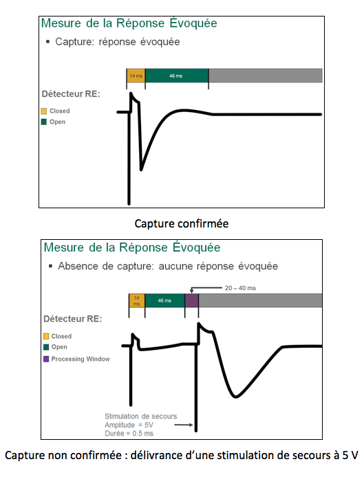
Pour vérifier l'existence de la capture, il y a une phase initiale de suppression de 14 ms, suivie d'une fenêtre de recherche de réponse évoquée de 46 ms. Si le dispositif détecte une réponse évoquée dans cette fenêtre, la capture est confirmée. Si aucun signal de réponse évoquée n'est détecté, l'appareil émet une impulsion de secours de 5 V dans les 80 à 100 ms suivant l'impulsion initiale pour assurer la capture.
Un test d'installation est nécessaire pour confirmer que le système AutoCapture fonctionne avec la sonde implantée. Ce test mesure la réponse évoquée et l'artefact de polarisation pour permettre une évaluation efficace de la capture. Il permet de déterminer une sensibilité de détection de l'ER appropriée. S'il existe une marge de sécurité suffisante entre la sensibilité de l'ER et la polarisation de la sonde, le fonctionnement d'AutoCapture sera fiable.
À la fin du test de configuration, l'appareil indique si la fonction AutoCapture est recommandée ou non.
Il reste la possibilité de changer le mode de détection et de stimulation (gamme Zephyr et supérieure) et/ou la durée d'impulsion, puis de recommencer le test.
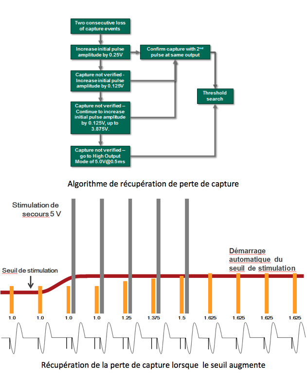
2. Récupération des pertes de capture
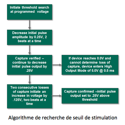
Si la vérification de la capture confirme deux pertes de capture consécutives, l'appareil lance l'algorithme de récupération des pertes de capture. Au cycle suivant, le stimulateur délivre une impulsion de sauvetage, puis augmente l'amplitude de l'impulsion automatique de 0,25 V et recherche une capture. Si aucune capture n'est confirmée, l'appareil augmente l'amplitude de l'impulsion de 0,125 V au cycle suivant et recherche une capture. Lorsque deux captures successives sont confirmées à la même tension, l'appareil commence une recherche de seuil.
Si aucune capture n'est confirmée avant que le dispositif n'augmente automatiquement l'amplitude de l'impulsion à 3,875 V, le dispositif passe en mode haute amplitude : l'amplitude de l'impulsion est réglée à 5 V et la durée de l'impulsion à 0,5 ms (ou plus si la valeur de programmation est plus élevée). Après 128 cycles, l'appareil commence une recherche de seuil.
3. Éviter les fusions
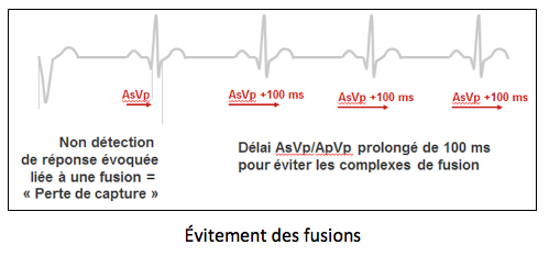
Les fusions avec AutoCapture doivent être évitées, car l'algorithme conclura que des pertes de capture se sont produites à la suite de l'élévation du seuil et déclenchera son algorithme de récupération des pertes de capture.
En mode double chambre, une seule absence de détection du RE, nécessitant la délivrance d'une impulsion de secours de 5 V, entraîne automatiquement l'allongement du délai AV stimulé et détecté de 100 ms au cours du cycle suivant, afin de rechercher une conduction spontanée. Dans un premier temps, l'algorithme “suppose” que la perte de capture est due à la fusion et non à un manque d'énergie de l'impulsion. Cette fonction agit de manière similaire à VIPTM.
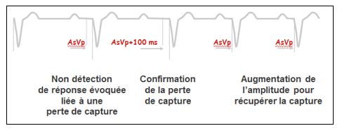
Si la perte de capture est confirmée après une prolongation du délai AV stimulé ou détecté (2 cycles consécutifs nécessitant la délivrance d'une impulsion de sécurité de 5 V), le stimulateur déclenche son algorithme de récupération de la capture :
4. Mesure périodique du seuil de stimulation
Lorsque la recherche automatique de seuil est lancée (toutes les 8h ou 24h), l'appareil diminue l'amplitude de l'impulsion de 0,25 V tous les deux cycles. Si cela entraîne une perte de capture, l'appareil émet une impulsion de secours de 5 V (marge de sécurité) 80 à 100 ms après la première impulsion de test. Si la capture est perdue sur deux cycles consécutifs à la même amplitude, l'algorithme augmente alors l'amplitude de l'impulsion par paliers de 0,125 V tous les deux cycles. Deux captures consécutives à la même amplitude doivent être confirmées pour déterminer la nouvelle valeur du seuil de stimulation. Lorsque la nouvelle valeur est trouvée, l'appareil détermine une nouvelle amplitude automatique en ajoutant une marge de travail de 0,25 V.
Si la recherche décroissante ne permet pas de déterminer une perte de capture au réglage d'amplitude d'impulsion le plus bas, c'est-à-dire 0 V, le dispositif passe en “mode haute amplitude” pour une durée de 128 cycles cardiaques, puis recommence la recherche de seuil.
Si le seuil de stimulation déterminé par l'algorithme dépasse 3,875 V pour une durée d'impulsion donnée, AutoCapture est automatiquement désactivé et l'amplitude de l'impulsion est reprogrammée à 5 V (mode haute amplitude). Dans ce cas, un réglage de durée d'impulsion plus élevé peut permettre de réactiver l'AutoCapture.
La recherche de seuil est répétée 1) après chaque opération de récupération en cas de perte de capture 2) automatiquement toutes les 8 heures 3) lors du retrait de la tête de télémétrie 4) lors du retrait de l'aimant 5) lorsque l'opérateur exécute le test de seuil du stimulateur via Autocapture™.
Pour éviter les fusions, le délai AV stimulé est programmé à 50 ms et le délai AV détecté à 25 ms. Les valeurs programmées sont rétablies lorsque la recherche est terminée.

Courbe de tendance montrant l'évolution du seuil sur un an
AGE enregistrée correspondant au seuil le plus récent
Biotronik
Principes de fonctionnement
- contrôle de la capture ventriculaire en marche : mesure du seuil de stimulation ventriculaire + adaptation de la programmation avec contrôle cycle par cycle ; contrôle de la capture ventriculaire en ATM : mesure du seuil de stimulation ventriculaire sans adaptation ; contrôle de la capture ventriculaire en arrêt : programmation fixe (aucun seuil automatique n'est réalisé)
- seuil ventriculaire effectué systématiquement tous les jours à 2h00 du matin (heure et fréquence de mesure programmables)
- vérification de la capture cycle par cycle basée sur l'analyse de la réponse évoquée
marge de sécurité programmable (valeur nominale + 0,5 V) - amplitude maximale pouvant être délivrée : 4,8 V pendant 0,4 ms
- amplitude minimale pouvant être délivrée : 0,7 V pendant 0,4 ms
Le contrôle des captures en pratique
Différents paramètres peuvent être programmés :
- l'amplitude de départ, qui correspond à la valeur de départ de la mesure du seuil ; valeur nominale 3 V (de 2,4 à 4,8 V) ;
- la marge de sécurité, qui correspond à la valeur ajoutée en amplitude à la mesure du seuil, valeur nominale 0,5 V (de 0,3 à 1,2 V) ; à noter que quelles que soient la valeur du seuil et la marge de sécurité, l'amplitude de stimulation ne peut descendre en dessous de 0,7 V ;
- l'heure de recherche et l'intervalle de recherche correspondent à l'heure à laquelle le seuil est systématiquement mesuré (valeur nominale 2h00), même en l'absence de perte de capture objectivée par le dispositif, et à l'intervalle entre chaque recherche minimale (valeur nominale 24 heures).
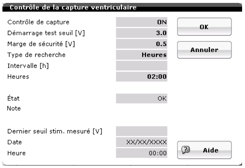
Le stimulateur cardiaque peut définir différents états pour la fonction de contrôle automatique de la capture ventriculaire : 1) “OK”, qui correspond à un fonctionnement correct ; 2) ‘disabled’ (pas de mesure de seuil), qui peut correspondre à 4 possibilités : a) plus de 25 pertes de capture en 24 heures b) impossibilité d'analyse du signal c) 3 échecs consécutifs d'analyse du signal et d) pacemaker en ERI ; 3) “high threshold” : comme le dernier seuil mesuré est supérieur à la valeur de départ, il est nécessaire d'adapter cette valeur de départ ; 4) “on hold” (le seuil ne peut temporairement pas être mesuré), qui peut se produire si la fréquence cardiaque est trop élevée au moment où la mesure devait être prise.
Le contrôle automatique s'effectue par étapes, avec la mesure de la réponse évoquée, la mesure de l'artefact de polarisation, la mesure du seuil par pas de 0,6 V, puis la mesure du seuil par pas de 0,1 V.
- mesure de la réponse évoquée et de l'artefact de polarisation : pour une évaluation efficace de la capture, il est essentiel de pouvoir faire la différence entre la réponse évoquée et l'artefact de polarisation.
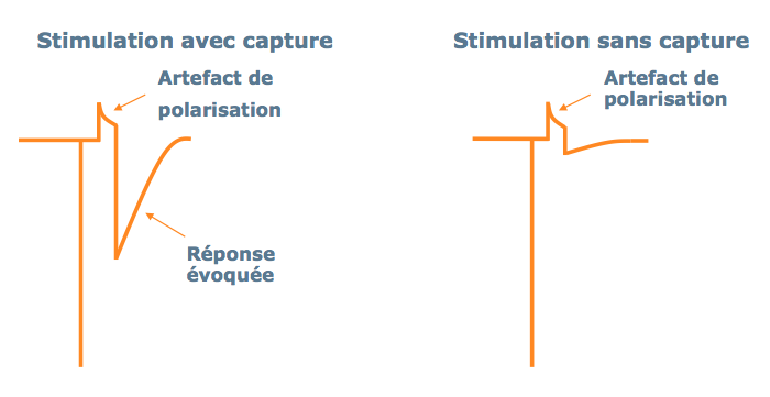
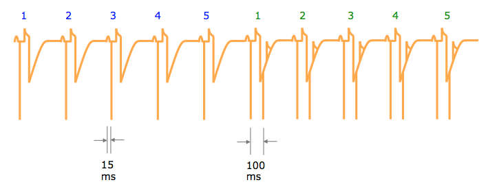
5 stimulations sont délivrées à la fréquence programmée avec un court délai AV (15 ms après la détection auriculaire et 50 ms après la stimulation auriculaire) pour assurer une capture ventriculaire efficace sans fusion et pour mettre en évidence la réponse évoquée et l'artefact de polarisation.
5 séquences de 2 stimulations ventriculaires avec le même délai AV sont ensuite délivrées avec un court couplage de 100 ms entre les 2 stimulations ventriculaires (sur la première, capture : évaluation de la réponse évoquée et de l'artefact de polarisation ; sur la seconde, pas de capture : évaluation de l'artefact de polarisation uniquement).
Pour différencier la réponse évoquée de l'artefact de polarisation, l'appareil analyse l'amplitude positive et négative des signaux, le moment où le signal traverse la ligne de base et les différentes intégrales du signal à différents moments.
L'analyse du signal est validée s'il existe une différence significative entre l'amplitude de la réponse évoquée et celle de l'artefact de polarisation.
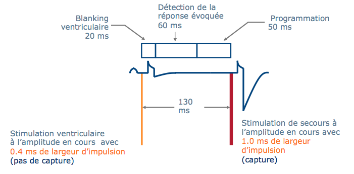
Pour vérifier l'existence de la capture, il y a une phase initiale de suppression de 20 ms, suivie d'une fenêtre de recherche de réponse évoquée de 60 ms, avec la possibilité d'une stimulation de secours après 130 ms s'il n'y a pas de capture.
Mesure du seuil de stimulation
Un seuil ventriculaire est fixé, avec une chute d'amplitude de 0,6 V pour chaque cycle ventriculaire. Lorsqu'une perte de capture est détectée, le test est répété à l'amplitude minimale assurant la dernière capture, avec une baisse d'amplitude de 0,1 V. Lorsqu'une perte de capture est détectée, un stimulus de sauvetage d'amplitude plus élevée se produit 100 ms après le premier (augmentation d'amplitude de 0,1 V avec une durée d'impulsion de 1 ms). Un deuxième stimulus de même amplitude que celui associé à la perte de capture est délivré. Si le deuxième stimulus capte, un troisième est délivré et l'amplitude continue de diminuer. Si le deuxième stimulus ne capture pas, une impulsion de sécurité est délivrée et le seuil est déterminé.
Une fois le seuil mesuré, l'amplitude de stimulation est automatiquement adaptée (marge nominale de 0,5 V), avec vérification cycle par cycle de l'efficacité de la capture.
Lorsqu'une absence de capture est diagnostiquée sur un cycle, une stimulation de secours a lieu 100 ms après la première (augmentation d'amplitude de 0,1 V avec une durée d'impulsion de 1 ms). Une modification du délai AV sur 3 battements est alors réalisée (AV delay extension) pour s'assurer de l'absence de fusion. Si la perte de capture persiste, le délai AV est à nouveau raccourci. Si 3 pertes de capture consécutives sont détectées, une nouvelle mesure du seuil est effectuée en adaptant l'amplitude à la nouvelle valeur.
Boston Scientific
Principes de fonctionnement
- Amplitude ventriculaire sur AUTO : mesure du seuil de stimulation ventriculaire + adaptation de la programmation avec contrôle cycle par cycle ; Amplitude ventriculaire sur valeur fixe et tendances journalières sur run : mesure du seuil de stimulation ventriculaire sans adaptation.
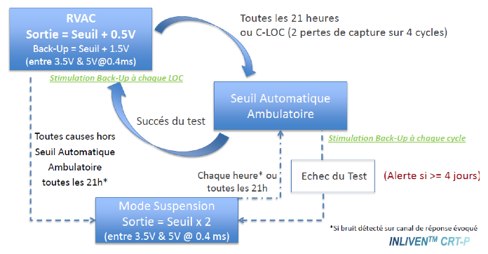
- seuil réalisé systématiquement toutes les 21 heures
- contrôle de la capture cycle par cycle basé sur l'analyse de la réponse évoquée
- marge de sécurité non programmable de + 0,5 V
- amplitude maximale pouvant être délivrée : 3,5 V pendant 0,4 ms
- amplitude minimale pouvant être délivrée : 0,7 V pendant 0,4 ms
Le contrôle automatique des captures en pratique
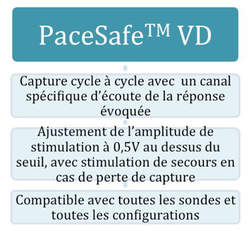
L'algorithme PaceSafe RV permet de tester automatiquement le seuil ventriculaire, en adaptant l'amplitude de stimulation à la valeur du seuil + 0,5 V et en vérifiant la capture cycle par cycle.
Un test de seuil automatique est effectué toutes les 21 heures. La durée de l'impulsion est fixée à 0,4 ms. L'amplitude de la stimulation ventriculaire est réglée avec une marge de 0,5 V au-dessus du seuil, avec une valeur minimale de 0,7 V et une valeur maximale de 3,5 V. Le seuil doit être compris entre 0,2 et 3 V.
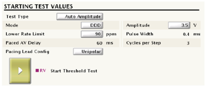
Pour mesurer le seuil, l'amplitude de la stimulation ventriculaire de départ est de 3,5 V, la durée de l'impulsion est fixée à 0,4 ms. Le délai AV stimulé est fixé à 60 ms, le délai AV détecté à 30 ms.
Le test commence par une phase d'initialisation (2 cycles d'échauffement pour calibrer l'évaluation de la mesure de la réponse évoquée, puis 12 cycles pour initialiser les filtres du canal de la réponse évoquée. Cette phase d'initialisation n'a pas lieu si la fonction AUTO Capture est déjà activée et qu'un seuil a déjà été mesuré en mode AUTO).
La mesure du seuil commence par une chute d'amplitude de 0,1 V tous les 3 battements. Le seuil de stimulation est déterminé lorsque 2 pertes de capture sur 4 cycles stimulés sont observées. Le deuxième cycle sans capture est marqué C-LOC (confirmed loss of capture). Le seuil de stimulation est fixé à la valeur précédant la perte de capture. Une stimulation de sécurité est effectuée à chaque perte de capture (70 ms après la première stimulation).
Une fois le seuil mesuré, l'amplitude de stimulation est automatiquement adaptée (marge nominale de 0,5 V), avec vérification cycle par cycle de l'efficacité de la capture.
Medtronic
Principes de fonctionnement
- contrôle du seuil ventriculaire droit sur dynamique automatique : mesure quotidienne du seuil de stimulation ventriculaire + adaptation de la programmation pendant 24 heures ; contrôle de la capture ventriculaire sur moniteur : mesure du seuil de stimulation ventriculaire sans adaptation ; contrôle de la capture sur stop : programmation fixe sans mesure de seuil
- seuil effectué systématiquement tous les jours à 1h00 du matin.
- seuil de stimulation basé sur l'analyse de la réponse évoquée
- une mesure quotidienne unique avec adaptation pendant 24 heures
- l'amplitude cible en multipliant la marge de sécurité de l'amplitude VD (programmable) par le seuil d'amplitude mesuré à une durée d'impulsion de 0,4 ms dans une plage de sortie définie par une limite inférieure programmable (paramètre d'amplitude minimale ajustée) et la limite de seuil supérieure de 5,0 V et 1,0 ms. La durée d'impulsion minimale pour le contrôle du seuil ventriculaire est de 0,4 ms.
- amplitude maximale pouvant être délivrée : 5 V pendant 1 ms
- amplitude minimale pouvant être délivrée : 1 V pendant 0,4 ms
Contrôle du seuil ventriculaire droit en pratique
Chaque jour à 1 heure du matin, le stimulateur effectue une recherche de seuil de stimulation ventriculaire afin de déterminer le seuil d'amplitude à une durée d'impulsion fixe de 0,4 ms. L'appareil évalue l'entraînement en détectant le signal de la réponse évoquée après chaque stimulation de test.
La recherche du seuil de stimulation commence à une amplitude de 0,125 V en dessous du dernier seuil mesuré. En l'absence de recherche précédente, la recherche commence à 0,75 V. L'appareil continue à diminuer l'amplitude par pas de 0,125 V jusqu'à ce que la capture soit perdue. Il augmente ensuite l'amplitude par pas de 0,125 V jusqu'à ce qu'il trouve une capture 3 fois de suite (ce qui correspond à la nouvelle valeur du seuil). Pendant la procédure de mesure du seuil, une stimulation de secours suit automatiquement chaque stimulation de test (que la capture ait eu lieu ou non), évitant ainsi la possibilité d'une pause ventriculaire pendant cette procédure. La stimulation de secours a lieu 100 ms après la stimulation de test, à l'amplitude programmée et avec une durée d'impulsion de 1,0 ms.
Une fois le seuil mesuré, l'amplitude de stimulation est automatiquement adaptée pour les 24 heures suivantes, sans vérification cycle par cycle de l'efficacité de la capture.
L'amplitude délivrée pendant ces 24 heures dépend des valeurs programmées pour les paramètres “marge de sécurité de l'amplitude VR” et “amplitude minimale ajustée VR”. Après une recherche réussie du seuil de stimulation, l'appareil calcule une amplitude cible en multipliant la marge de sécurité de l'amplitude VR par le seuil d'amplitude mesuré à une durée d'impulsion de 0,4 ms.
Cette adaptation ne peut avoir lieu qu'à l'intérieur d'une plage de sortie définie par une limite inférieure programmable (paramètre Amplitude minimale ajustée) et la limite supérieure du seuil de 5,0 V et 1,0 ms. La durée minimale de l'impulsion pour le contrôle du seuil ventriculaire est de 0,4 ms.
Si le seuil ventriculaire est mesuré à 0,4 V pendant 0,4 ms avec une marge de sécurité minimale de 2 fois le seuil et une amplitude minimale de 2 V, l'amplitude délivrée est de 2 V pendant 0,4 ms.
Si le seuil ventriculaire est mesuré à 1,4 V pendant 0,4 ms avec une marge de sécurité minimale de 2 fois le seuil et une amplitude minimale de 2 V, l'amplitude délivrée est de 2,8 V pendant 0,4 ms.
Si le seuil ventriculaire est mesuré à 3 V pendant 0,4 ms avec une marge de sécurité minimale de 2 fois le seuil et une amplitude minimale de 2 V, la durée de l'impulsion est augmentée pour obtenir un nouveau seuil. Si le nouveau seuil ventriculaire est mesuré à 2,5 V pendant 0,8 ms, l'amplitude délivrée est de 5 V pendant 0,8 ms (marge de sécurité respectée).
Microport
Principes de fonctionnement
- autoseuil on auto : mesures régulières du seuil de stimulation ventriculaire + adaptation de la programmation ; autoseuil on suivi : mesures régulières du seuil de stimulation ventriculaire mais sans adaptation de la programmation ; autoseuil on non : pas de mesure de seuil et valeur fixe ;
- seuil effectué systématiquement toutes les 6 heures sur la base de l'analyse des réponses évoquées
- 4 mesures de seuil par jour avec adaptation pendant les 6 heures suivantes (pas de vérification cycle par cycle)
- adaptation automatique de l'amplitude au double de la valeur seuil (marge de sécurité de 100%) dans la limite d'une valeur minimale programmable (1,5, 2, 2,5, 3, 3,5 ou 4 V)
Seuil automatique ventriculaire en pratique
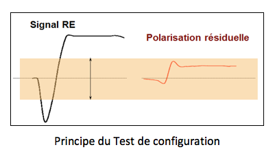
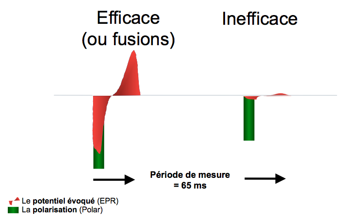
Le test de capture est basé sur la différenciation entre le potentiel évoqué (EPR) et la polarisation résiduelle de la sonde (Polar).
Après un stimulus efficace, pendant une période de 65 ms, les deux potentiels sont présents (EPR + Polar) et mesurables, alors qu'après un stimulus inefficace, seule la polarisation résiduelle de la sonde est présente (Polar) et mesurable.
Phase d'attente
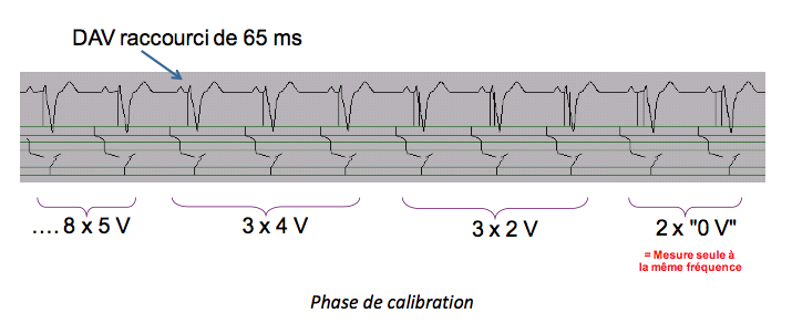
L'objectif de cette phase est de stabiliser le rythme ; 8 stimulations à 5 V sont délivrées.
Phase d'étalonnage
L'objectif de la phase d'étalonnage est double :
- Identifier un seuil de stimulation initialement élevé (supérieur à 2V)
- Évaluer la mesure de la réponse évoquée
Afin d'augmenter la probabilité de capturer le ventricule, le délai AV actuel est raccourci de 65 ms (stimulateur double chambre) ou l'intervalle d'échappement est raccourci de 65 ms (stimulateur simple chambre).
Trois stimulations à 4 V (à la largeur d'impulsion programmée) sont délivrées, et seules les deux dernières sont suivies d'une mesure de la réponse/polarisation du potentiel évoqué.
Trois stimulations à 2 V (à la largeur d'impulsion programmée) sont délivrées, et seules les deux dernières sont suivies d'une mesure de la réponse/polarisation du potentiel évoqué. Ces 3 stimulations à 2 V sont chacune suivies, après la période de mesure (65 ms), d'une stimulation de sécurité à 2,5 V avec une largeur d'impulsion de 1 ms. Le but de ces séances de stimulation de sécurité est d'assurer la capture ventriculaire si le seuil de stimulation dépasse 2 V. Si ces deux séries donnent des mesures acceptables et comparables, le stimulateur applique l'étape suivante.
Deux “stimulations 0 V” sont effectivement suivies d'une période de mesure de la réponse/polarisation du potentiel évoqué ; elles permettent de diagnostiquer la fusion qui peut altérer la mesure du seuil. En effet, si des potentiels évoqués spontanés sont mesurés après une “stimulation 0 V”, ils témoignent de la présence d'une éventuelle fusion ou de dépolarisations ectopiques lors des mesures précédentes (à 2 et 4 V). La phase d'étalonnage est alors répétée avec un court délai AV (65 ms) pour éviter la fusion. Si, malgré cet ajustement, la fusion est toujours détectée, le test est arrêté et la tension ventriculaire est forcée à 5 V pendant les six heures suivantes.
Phase de mesure du seuil de stimulation ventriculaire
Une fois l'étalonnage terminé, le test de seuil de stimulation commence à 1,95 V avec un décrément de 0,15 V jusqu'à ce que la tension de perte de capture ou le minimum de 0,15 V soit atteint. Chaque stimulation est suivie d'une période de mesure (65 ms). Si une perte de capture est détectée, une stimulation de sécurité à 2,5 V avec une largeur d'impulsion de 1 ms est délivrée.
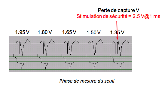
Dans cet exemple, le seuil V est de 1,5 V. L'amplitude est programmée à 3 V pour les 6 heures suivantes. La valeur de 1,5 V est affichée sur la courbe de seuil automatique, ainsi que la tension de stimulation appliquée pendant les 6 heures suivantes.
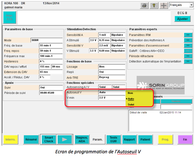
Programmation
Le seuil ventriculaire automatique n'est pas disponible en mode SafeR. Il est exécuté si la fréquence cardiaque est inférieure à 95 min-1. L'amplitude de stimulation ventriculaire n'est pas programmable lorsque V Auto-threshold est réglé sur “Auto”. Les valeurs de durée d'impulsion ventriculaire supérieures à 0,5 ms ne peuvent plus être programmées lorsque la fonction V Auto-threshold est réglée sur “Follow-up” ou “Auto”. Le délai de repos AV est reprogrammé à 125 ms s'il avait auparavant une valeur inférieure à 125 ms.
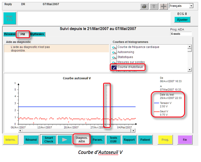
Suivi du seuil de stimulation V dans les mémoires
Sur l'écran AIDA Diagnostics, dans l'onglet PM, cliquer sur le bouton AutoMoil Curves permet d'afficher la courbe de valeur moyenne des 4 mesures quotidiennes de la fonction V Auto-threshold. La tension de sortie ventriculaire appliquée est indiquée en parallèle.
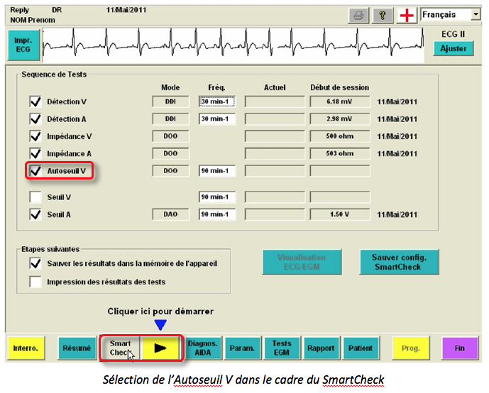
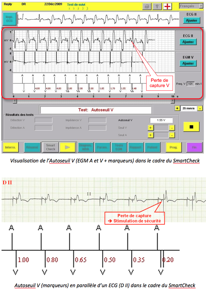
Lors des contrôles de l'appareil, l'Auto-threshold V (avec une phase d'étalonnage et une tension de départ légèrement différentes) fait partie de la séquence automatique de mesures de la sonde, avec l'affichage de l'EGM pour confirmation. Cette séquence optionnelle est appelée SmartCheck.