Left ventricular stimulation

Basic concepts


LEFT VENTRICULAR STIMULATION


The left ventricle can be stimulated from 4 different approaches: 1) subepicardial, with the lead implanted transvenously via a coronary sinus tributary, 2) endocardial, with the lead implanted transseptally, 3) epicardial, with the lead implanted surgically, and 4) intrapericardial, with the lead implanted transcutaneously. The transvenous approach is used preferentially in the majority of medical centers. The coronary sinus drains nearly the entire left ventricle from 4 main tributaries: 1) the inferior, the posterior, the lateral, and the great cardiac vein(s). The anterior aspect of the left ventricle and the septum are drained by the anterior interventricular vein, while the lateral walls are drained by the postero-lateral, antero-lateral and lateral veins. The atria are also drained by several veins (of which the main is the vein of Marshall) into the coronary sinus. The length, diameter and orientation of the coronary sinus are highly variable; consequently, the challenge represented by each device implantation is unpredictable. Several valves may obstruct or narrow the coronary sinus. The valve of Thebesius is near the ostium, while that of Vieussens is near the ostium of the first postero-lateral vein. The phrenic nerve courses along the lateral veins, along the posterior branches of an anterolateral vein, and along the anterior branches of a postero-lateral vein. 

The several steps of a device implantation procedure include the a) venous access, b) introduction of a guiding sheath in the right atrium, c) cannulation of the coronary sinus, d) opacification and selection of the target vein, e) implantation of the lead, and b) removal of the sheath. In recent years, new leads of various shapes and sizes have been developed. Once the venous network has been opacified, a stimulation lead is chosen that corresponds closely to the anatomical characteristics of the target vein. This choice is determined by the sizes of the ostium and body of the target vein, such that the lead diameter and size of the vascular internal lumen fit tightly. Some variables, such as a high capture threshold or the likelihood of diaphragmatic stimulation are unpredictable, though, ultimately, have an influence on the choice of stimulation site and, therefore, on the choice of optimal lead.


Configuration of left ventricular stimulation

The various programming options available enable the selection of a LV stimulation polarity associated with a reliable and durable myocardial capture with the least amount of power necessary in order to maximize the longevity of the device, without stimulating the phrenic nerve. The programming of the stimulation amplitude must optimize the battery life while preserving a sufficient safety margin. The LV epicardial stimulation threshold is often higher (twice as high in one study) and more variable than the RV stimulation threshold. It might not be possible to obtain a safety margin as high as twice the capture threshold since, when >2.0 V, the batteries will likely be prematurely depleted. In some patients the stimulation amplitude and pulse width must be meticulously programmed to capture the left ventricle without phrenic nerve stimulation. The influence of the LV stimulation configuration on the quality of response to cardiac resynchronization remains to be determined and rarely represents a selection criterion.

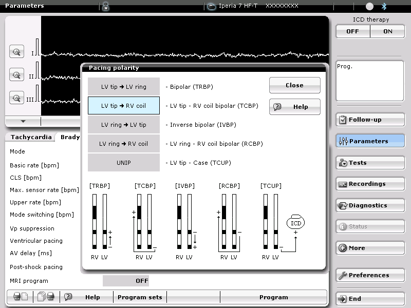
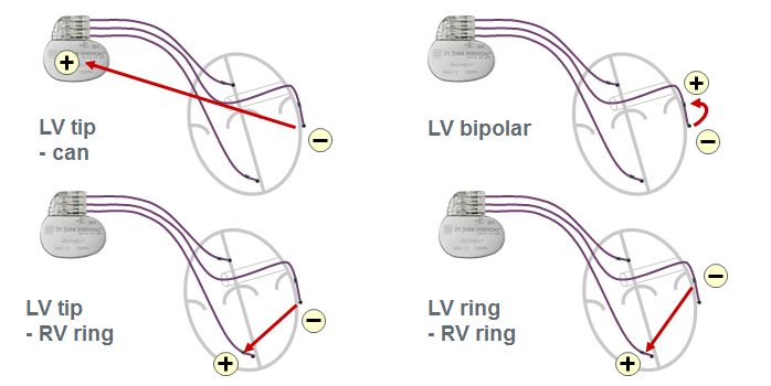
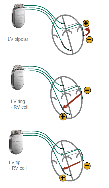
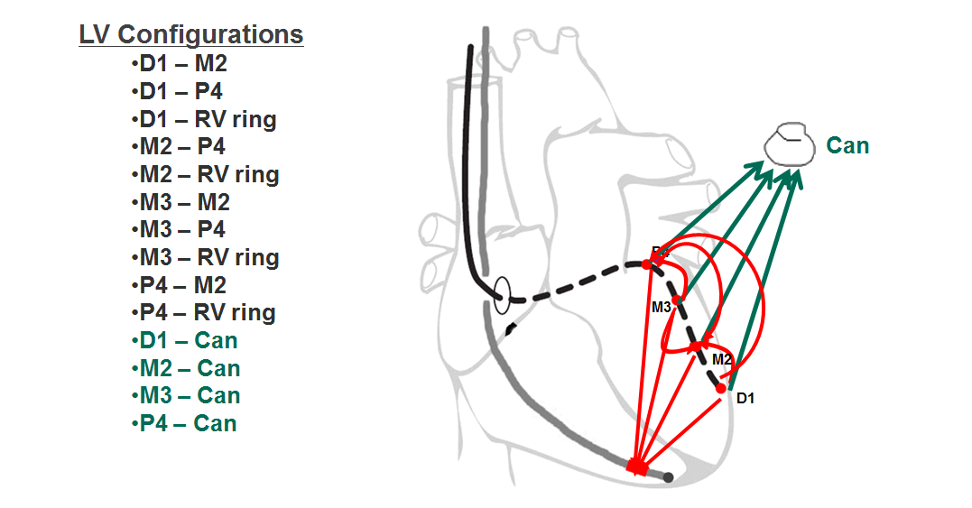
The armamentarium offered by the various device manufacturers includes uni-, bi- and quadripolar LV leads. The stimulation polarity is programmable in the left ventricle by choosing a quadripolar (4 electrodes) or non-quadripolar (1 or 2 electrodes) lead. If a unipolar LV lead is implanted, a single configuration (LV tip à RV ring or RV coil) might be programmable depending on the manufacturer and type of device. With most defibrillators, the RV coil is used instead of the RV ring. With CRT-P, the RV ring (proximal electrode of a bipolar lead) is used. With some devices and, depending on the manufacturer, the pulse generator may participate in the stimulation vector, offering the programming of LV tip à pulse generator (can) as second choice of stimulation configuration. If a bipolar LV lead is implanted, between 3 and 6 configurations are available depending on the manufacturer and type of device. The threshold is often higher with LV ring à RV coil configuration and the distal LV electrode (cathode) is preferentially used as the active electrode, while the RV coil or LV ring (anode) are used as the indifferent electrode. If a quadripolar LV lead is implanted, between 12 and 17 configurations are available depending on the manufacturer and the type of device. This multitude of choices allows an optimization of the capture threshold and a lower likelihood of phrenic nerve stimulation. With a wide spacing of the electrodes, the activation sequence can be varied, for example by choosing a distal (apical) versus proximal (basal) electrode. This choice may have a positive impact on the response rate, despite the paucity of criteria objectively predictive of the quality of response to therapy. St. Jude Medical makes the only devices, which offer a choice of dual site LV stimulation, as an increase in the number of stimulated sites is likely to decrease the activation dyssynchrony.


Anodal capture

The pulse strength influences the likelihood of anodal capture. The cathode at the tip of the LV lead is usually smaller than the anode, explaining the high current density at that site. A strong pulse may create a high enough current density to capture the tissue near the anode. The RV ring of CRT-P is often used as anode to stimulate the left ventricle. A high-amplitude stimulation may cause an anodal RV capture resulting in triple-point stimulation: LV and RV cathodes + RV anode. Anodal capture is more likely when the LV stimulation configuration includes a true RV bipolar lead (lead ring) instead of an integrated bipolar lead (since the anode is the distal coil), probably because the small size of the ring promotes a higher current density. The electrocardiographic morphology is often slightly modified compared with the usual BiV appearance. A 12-lead electrocardiogram, instead of the single channel of the programmer, is usually needed for the diagnosis. On the other hand, an anodal capture may considerably modify the analysis of the tracings during the LV threshold test. The hemodynamic effect of this type of stimulation, which increases the number of stimulated sites, might be positive, though the clinical results remain to be seen. An anodal capture usually requires strong stimulation pulses, which shorten the devices’ life expectancy.


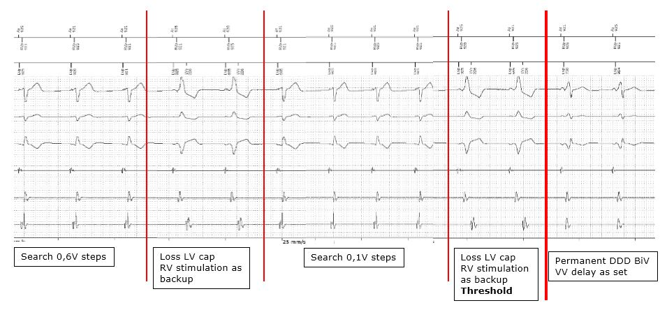
Automated left ventricular threshold

The function of the automated LV threshold is often very close to that described for the RV lead. The threshold measurement is based on the analysis of the evoked response, or by observing the synchronization of the RV events sensed after a stimulated LV event. The threshold is measured at regular intervals of between 8 and 24 h, depending on the manufacturer, after which a safety margin is programmed, without further cycle-by-cycle verification of capture. It is noteworthy that triple chamber devices do not verify the cycle-by-cycle LV or RV lead capture.    

Specificities

Biotronik

Unipolar lead

When an unipolar LV lead is implanted, the 2 configurations that can be programmed on a CRT-P or CRT-D are the LV tip à pulse generator and the LV tip à proximal RV. With the Ilesto CRT-P or CRT-D models, the proximal RV electrode is the ring of the RV lead (proximal electrode), whereas with the new defibrillator models, the RV electrode is the coil of the RV lead (likewise for the bipolar and quadripolar configurations).

Bipolar lead

The 2 electrodes are the LV tip and ring. When a bipolar LV lead is implanted, 5 configurations can be programmed on the triple chamber defibrillators (shown on the following figure). With a CRT-P, a 6th LV ring à pulse generator configuration can be added.

Configurations available with triple chambre defibrillators

Quadripolar lead

This lead can accommodate 12 different configurations.

Automated LV threshold

Threshold measurements are based on an analysis of the evoked response, without cycle-by-cycle verification of capture. The threshold is measured once daily at a programmable time (default = 2:00 AM), beginning at a programmable amplitude (default = 3.0 V), and decreasing initially in 0.6 V, followed by 0.1 V steps. During the threshold measurement, the VV delay is programmed at 50 ms (LV preexcitation). Once LV capture has been lost, RV stimulation occurs at the end of the VV delay, to eliminate the risk of asystole in pacemaker-dependent patients.

Once the LV threshold stimulation measured, a safety margin is set for the next 24 h.


Boston Scientific

Unipolar lead

After the implant of an unipolar LV lead, 2 programming choices are available, since the pulse generator can be included in the stimulation vector.

Bipolar lead

The 2 electrodes are the distal and proximal LV. After the implant of a bipolar LV lead, 6 programming configurations are available.

Quadripolar lead

The 4 electrodes are labeled dist LV1, prox LV2, prox LV3 and prox LV4, with dist LV1 as the most distal electrode, and 17 different programming configurations are available.

Automatic left ventricular threshold

The PaceSafe LV function is available for all unipolar and bipolar stimulation configurations, though is not available with the IS4 (quadripolar lead) defibrillators.

In the ambulatory setting, the threshold is automatically measured every 21 h with the following programmed settings: paced AV delay at 140 ms; sensed AV delay at 110 ms; rescue RV stimulation occurs throughout the LV test with an 80 ms LV preexcitation. The initial amplitude corresponds to the programmable maximum amplitude, decreasing in 0.5-V steps above 3.5 V, and in 0.1-V steps below 3.5 V.

The measurement of the threshold is based on an analysis of the evoked response. The evoked response channel is an unipolar sensing channel that utilizes the distal or proximal LV electrode, depending on the programmed stimulation configuration. Should the daily test fail, the LV PaceSafe function returns to the previously measured output, and up to 3 new attempts are then made, at hourly intervals. Should the daily test fail over 4 consecutive days, a lead alert is triggered and the PaceSafe LV function switches to “Failure” mode (delivered output = 5 V/0.4 ms).

If the automatic adaptation has been programmed, following the measurements made at 21 h intervals, the output is then adapted with a programmable safety margin between 0.5 and 2.5 V, without cycle-by-cycle verification of capture. Instead of being adapted relatively to the very last measurement, the LV stimulation output is set with a programmable safety margin added to the threshold measured at the time of the last 7 successful tests performed during ambulatory follow-up. This enables a rapid increase in stimulation amplitude, should the threshold increase suddenly. It is noteworthy, that a single low threshold measurement does not lower the stimulation amplitude.


Medtronic

Unipolar lead

With a unipolar LV lead, the new generation of defibrillators (CRT-D) offer the distal LV tip à RV coil as the only programmable choice, excluding the pulse generator from the stimulation circuit. With CRT-P, however, stimulation can be programmed between the distal LV electrode and the pulse generator.

Bipolar lead

The 2 electrodes are the LV tip and LV anode. After the implantation of a bipolar LV lead, the new generation of defibrillators offer 4 programmable options, including LV tip à RV coil, LV anode à RV coil, LV tip à LV anode, and LV anode à LV tip.

Quadripolar lead

The 4 electrodes of a quadripolar lead are LV1 (most distal), LV2, LV3 and LV4, which offer 16 different stimulation configurations.

The VectorExpress LV Automated test

This test, available with devices that accommodate quadripolar leads, simplifies the choice of configurations by measuring automatically impedance and LV capture threshold with a variety of polarities. The results of the test include the capture threshold, the estimated effect of the programming on device longevity, the lead impedance at each polarity and, if desired, the threshold of phrenic nerve stimulation. These results are used to optimize the stimulation polarity, set the pulse amplitude and duration, guarantee the control of the threshold test, limit the energy consumed and, thereby, optimize the device longevity.

The VectorExpress LV automated test conducts a threshold search to determine the LV stimulation amplitude threshold at the selected pulse width for each selected LV pacing polarity. The test varies the pulse amplitude in search of the LV myocardial capture threshold. The device estimates the LV threshold by observing the right ventricular-coupled event sensed after LV stimulation. If a RV event is sensed during the threshold test, the result is "captured". If no RV response is sensed, the result is "loss of capture". If the results remain inconclusive or too many intrinsic events occur, the test is aborted with this specific pacing polarity and progresses to the next one. A stimulation threshold test is performed for each polarity of LV stimulation selected, at a 2.5-V initial amplitude. The search process varies thereafter, depending on whether this 2.5-V test amplitude is above or below the LV stimulation threshold. If the 2.5-V test amplitude is above the stimulation threshold, the device lowers the amplitude in 0.25-V decrements, until below the LV threshold or until the minimum 0.25-V test amplitude has been reached. If the 2.5-V test amplitude is below the LV threshold, the stimulus amplitude is increased to 6.0 V. If it remains below the stimulation threshold, the test indicates that the threshold is >6.0 V for that polarity. Otherwise, the device lowers the amplitude in 0.5 V decrements until below threshold or until a minimum of 3 V has been reached. The last test amplitude above threshold defines the threshold for that LV stimulation polarity.

The test of the 16 possible vectors takes 2 to 3 min. The polarities known to stimulate the phrenic nerve can be excluded.

Automated LV threshold

LV Capture Management is scheduled daily at 1:00 a.m. Unlike the RV threshold where the evoked response serves to identify the capture, the device observes the synchronization of sensed RV events after stimulated LV events as an indication that capture has occurred.

Control of the threshold takes place in 4 stages: 1) Control of the rhythm and rate stability; the variability of the RR intervals must be <200 ms, and the rate <90 bpm; 2) measurement of the conduction delay between LV stimulation and sensed RV event (8 synchronized, LV stimulated events after sensed or paced atrial events at a rate 15 bpm above that measured during stage 1); 3) measurement of the delay between paced atrial and sensed RV events; 4) measurement of the LV threshold.

The stimulation threshold search begins at a test amplitude 0.125 V below the last measured threshold. In absence of previous search, a new search begins at 0.75 V. The device decreases the test amplitude in 0.125-V steps to a value below the capture threshold, then increases the test amplitude in 0.125-V steps, until it exceeds the capture threshold 3 times consecutively. This test amplitude is the LV capture threshold.

With each measurement of the threshold, the stimulation test is part of a test sequence. In a test sequence, 3 support cycles precede the stimulation test. The support cycles stimulate the left ventricle at an amplitude equal to the permanent amplitude or at the programmed setting for the maximum LV adapted amplitude.

If the LV capture management is set on “Auto”, the device automatically adjusts the LV amplitude. After a successful pacing threshold search, the device calculates a target amplitude by adding the programmed LV amplitude safety margin to the threshold amplitude. In addition to the ongoing amplitude threshold and the target amplitude, amplitude adjustment may depend on the last measured threshold amplitude and the programmed LV maximum adapted amplitude. There is no programmable lower limit. Beyond 5 V, the adapted amplitudes are rounded to the nearest 0.5 V.

In a pacemaker-dependent patient (in complete AV block), the control of the LV threshold may generate an atrial event without ventricular capture.


Abbott

Unipolar lead

A CRT-P connected to a unipolar LV lead enable 2 unipolar configurations, including a) distal LV à can, and b) distal LV à RV ring. However, CRT-D enable only 1 configuration, i.e. distal LV à RV coil.

Bipolar lead

A CRT-P connected to a bipolar lead enables 1 bipolar (distal à proximal LV) and 3 unipolar configurations, including a) distal LV à can, b) distal LV à RV ring, and c) proximal LV à RV ring.


A CRT-D connected to a bipolar lead enables 1 bipolar (distal à proximal LV) and 2 unipolar configurations, including a) distal LV à RV coil and b) proximal LV à RV coil.

Quadripolar lead

A CRT-P connected to a quadripolar lead enables 14 different configurations. From most distal to proximal, the 4 electrodes are Distal 1, Mid 2, Mid 3 and Proximal 4.

A CRT-D connected to a quadripolar lead enables 10 different configurations.

Dual site LV stimulation can be performed by selecting 2 LV stimulation vectors simultaneously.

Automated LV threshold

The automated measurement of the LV threshold in the ambulatory setting is programmable between every 8 to 24 h. The measurement is based on the sensing of the 1st derivative of the evoked response signal, which must be tested in order to adjust its sensitivity. When the automated adaptation has been activated, after every 8 to 24 h measurements, the delivered pulse amplitude is adapted with a programmable safety margin between 0.25 and 2.5 V (nominal = 1.0 V) without cycle-by-cycle verification of capture.


Microport CRM-Sorin

The last generation devices, including INTENSIA, PARADYM, PARADYM RF and PARADYM 2 can be connected to unipolar or bipolar LV leads. In a unipolar, a single Distal LV à Proximal RV vector is available. In a bipolar configuration, 3 vectors are available, including a) Distal à Proximal LV, b) Distal LV à Proximal RV, and c) Proximal LV à  to RV coil.

By the end of year 2015, the next generation of devices will offer 6 LV vectors with a bipolar IS-1 lead and 14 vectors with a quadripolar IS-4 lead.